![]()
![]()
Section 3.3 Cutting front geometry prediction
Lasers has been demonstrated as particular effective for high speed material removal and for materials which are difficult to mechanically process due to harness, adhesiveness, brittleness, and so on. Laser cutting is one of the most commonly used laser machining process. In laser cutting, a relative motion between an impinging laser source and a workpiece generates a kerf which penetrates through the entire workpiece. The mechanisms influencing material removal differ depending on the target material, gas jet condition and laser energy. Laser cutting can be divided into evaporative cutting, fusion and reactive cutting, please refer to Section 3.1 Level 1 for a brief introduction on laser cutting.
The cutting-front geometry prediction is an important part of the modeling work in laser cutting. Some simple models were based on power balance between surface absorption, material melting, material heating and material conduction, and a constant kerf width equal to beam diameter, semi-circular cutting front contour and constant inclined angle were assumed. In this section, we introduce a generalized model describing the mechanisms which influence laser evaporative and fusion cutting. Issues such as finite workpiece thickness, beam divergence, surface absorption of the beam and plasma absorption will be considered. Thus, given a set of laser operating parameters, the shape and size of the cutting front can be estimated.
The main effects which influence material removing during laser cutting are illustrated in Figure 3.54. Incident laser energy is partially absorbed by plasma above the cutting front, the surface of the cutting front also reflects a portion of the beam energy, the remaining incident energy is balanced by heat conduction into the bulk material and the phase changes at the cutting front surface. This phase chane propagates the kerf and results in material removal. Other factora include convection and secondary reflections of the beam energy.
The following assumptions are used to develop the general model for front geometry prediction in laser cutting:
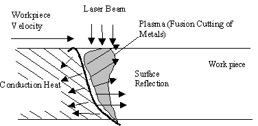
Figure 3.54: Effects influencing laser cutting
Part 1: Kerf geometry definition
As illustrated in Figure 3.55, the cutting front can be divided into piece-wise linear surface elments with area dA and surface normal n, and each finite surface element can be described by inclination angles q in the x-direction and f in the y-direction. The projection of this element on the x-y plane has area dxdy, the area dA is bounded by two vectors p and q, the surface normal is:
![]()
And ![]()
Thus we have an expression for dA:
![]()
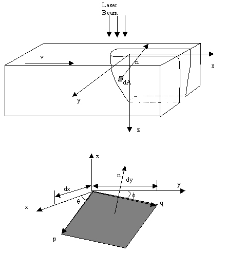
Figure 3.55: Orientation of the surface element
Part 2: Energy balance at the cutting front
An energy balance exists at each surface element between incident laser energy Eb, conduction of heat through the surface into the bulk material Econd and phase change Ep.
Eb(x,y)dxdy = Econd(x,y)dA+Ep(x,y)dxdy
The cumulative beam energy at a given point is the time integral of laser intensity. Assuming a constant workpiece velocity V, we have dt=du/V, where u is a reference coordinate in the x-direction. Assuming TEM00 mode Gaussian beam intensity with a(x,y) as the beam absorption coefficient, P as peak intensity, R the beam radius, we have:
From above equation, we see the absorbed incident energy is related to absorptivity and beam radius. Absorptivity is affected by surface element orientation and plasma density. Beam radius is related to beam divergence and the distance from the beam waist location.
The energy of phase change can be expressed as the energy required to heat the material from room temperature to the melting or vaporization temperature Tp. The mass involve is the column of material with a cross section area of dxdy extending from the workpiece top surface to the local position of the surface leement on the cutting front s(x,y):
![]()
The conduction effects are three dimensional and computation intensive. The assumption of normal direction conduction is used here since the main factor influencing conduction energy if the temperature gradient and this gradient is largest in the normal direction. Considering the finite workpiece thickness D, the heat conduction length in the normal direction d is defined (Figure 3.56):
![]()
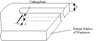
Figure3.56: Definition of conduction depth
Assuming a steady-state process, considering the relative motion between the workpiece and the beam to be along the x-direction with constant velocity V, we have the governing equation:
![]()
From the geomtry relations between x and n, the above equation can transformed into an ordinary differential equation:
The boundary conditions are:
T=Tp at n=0
![]() at n=d
, the end of conduction length.
at n=d
, the end of conduction length.
After solving this PDE, the conduction energy can be determined as the path integral of the conduction heat flux in the x-direction:
Taking the three energy components into the energy balance relation, we get the equation governing the cutting front geometry:
The above equation can be solved numerically to get the cutting front geometry
at any location s(x,y). The parameters are a, s, ![]() ,
R,
,
R, ![]() and
and ![]() .
.
Part 3: Illustration
Using above algorithm, the three dimensional shape of the cutting front can be computed. Figure 3.57 shows the three-dimensional shape of the cutting front on PMMA for different power conditions. For a low energy density condition such as 200W laser power and 17.8 mm/s velocity, the laser beam barely penetrates through the workpiece thickness as shown in figure 3.57 (a). This creates a cutting front geometry with Gaussian centerline and profile and a narrow kerf bottom. For higher energy intensity such as 200W laser power and 2.55mm/s velocity, much deeper centerline and kerf walls are produced as shown in figure 3.57(b). The resulting kerf has a much wider kerf bottom (L. Cai and P. Sheng, 1994).
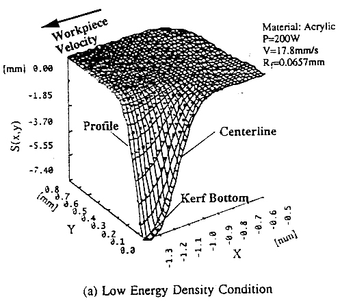
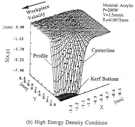
Figure 3.57: Model estimates of three-dimensional cutting fronts of PMMA (a) Low energy density condition; and (b) High energy condition
(Li, Cai and Sheng, P., 1994)
References:
Biyikili, S. and M. Modest, 1988, "Beam expansion and focusing effects on evaporative laser cutting," ASME J. Heat Transfer, Vol. 110, No. 2, pp. 529-532.
Chryssolouris, G.,1991, Laser Machining: Theory and Practice, Springer-Verlag, New Yok.
Li, Cai and Sheng, P., 1994, "Analysis of laser evaporative and fusion cutting," ASME, PED-Vol. 68-1, Manufacturing Science and Engineering.
Li, Kezhun and Sheng, P., 1995, "Computational model for laser cutting of steel plates," ASME, Med-Vol. 2-1/MH-Vol. 3-1, Manufacturing Science and Engineering.
Petering, D., et al., 1988, "The Absorption distribution as a variable property during laser beam cutting," ICALEO '88, pp. 293-302.
D. Pietro, P. and Yao, Y. L., 1994, "An investigation into characterizing and optimizing laser cutting quality--a review," Int. J. Mech. Tools Manufact., Vol. 34, No. 2, pp. 225-243.
D. Pietro, P. and Yao, Y. L., 1995, "A numerical investigation into cutting front mobility in CO2 laser cutting," Int. J. Mech. Tools Manufact., Vol. 35, No. 5, pp. 673-688.