![]()
![]()
![]()
Level 1
Section 5.3: Introduction to laser machining of composites (I)
Composites are structures in which two (or more) materials are combined to produce a new material whose properties would not be attainable by conventional means. Examples include plywood, concrete, and steel belted tires. The most prevalent applications for fiber reinforced composites are as structural materials where rigidity, strength, and low density are important. Many tennis rackets, racing bicycles, and skis are now fabricated from a carbon fiber-epoxy composite that is strong, light, and only moderately expensive. In this composite, carbon fibers are embedded in a matrix of epoxy, as shown in Figure 1. The carbon fibers are strong and rigid but have limited ductility. Because of this brittleness, it would not be practical to construct a tennis racket or ski from carbon alone. The epoxy, which in itself is not very strong, plays two important roles. It acts as a medium to transfer load to the fibers, and the fiber-matrix interface deflects and stops small cracks, thus making the composite better able to resist cracks than either of its constituent components.
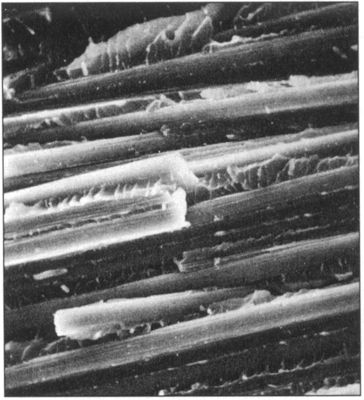
Fig. 1 A cross section view of a carbon-epoxy composite showing the strong and stiff graphite fibers embedded in the tough epoxy matrix (By Behawan D.Agrawal and Lawrence J.Broutman. Analysis and perfrmance of Fiber composites)
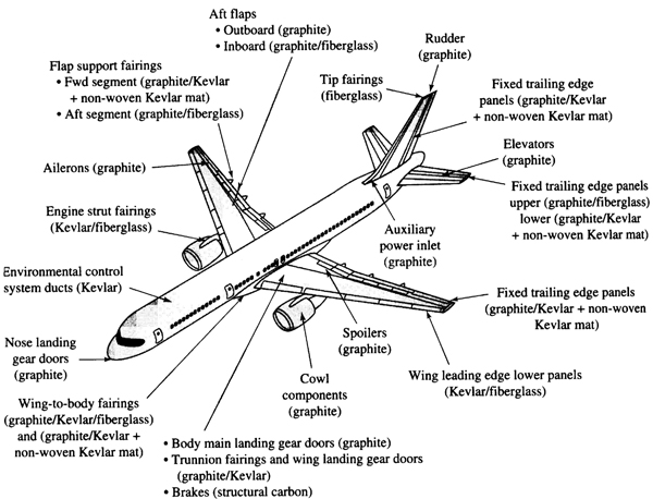
The strength and rigidity of a composite can be controlled by varying the amount of carbon fiber incorporated into the epoxy. This ability to tailor properties, combined with the inherent low density of the composite and its (relative) ease of fabrication, makes this material an extremely attractive alternative for many applications. In addition to the sporting goods described above, similar composites are used in aerospace applications such as fan blades in jet engines (where the operating tempera- tures are low) and for control surfaces in airframes. The use of composites in the Boeing 757 aircraft is shown in Figure 2.
Fig. 2 List of Composite ports in the main structure of the boeing 757-200 aircraft.(Source: Boeing commercial Airplane company)
Composites can also be fabricated by incorporating strong ceramic fibers in a metal matrix to produce a strong, rigid material. An example is SiC fibers embedded in an aluminum matrix. Such a composite, known as a metal-matrix composite, finds application as an airframe material for components in which moderate loads are encountered, such as in the skin of the fuselage. Composites in which metal fibers are embedded in a ceramic matrix (ceramic- matrix composites) are produced in an attempt to take advantage of the strength of the ceramic while obtaining an increase in the toughness from the metal fibers that can deform and deflect cracks. When a crack is deflected, more load is required to make it continue to propagate, and the material is effectively tougher. Some exciting new developments and possibilities for composites include: There is great potential to reduce the weight and increase the payload of airplanes. Initial uses are for lightly loaded parts such as vertical stabilizers and control surfaces made from carbon fiber-epoxy, but metal-matrix com- posites will play an increasingly important role. High-temperature ceramic-matrix composites will increase operating temperatures of engines. A significant challenge in increasing the use of composites is to learn to design with materials having totally different modes of failure than do conven- tional materials.
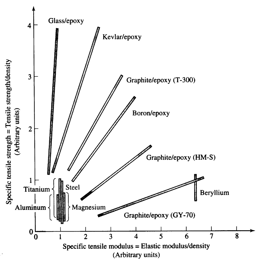
For any class of fiber reinforced composites the ones with the highest specific strength and modulus values generally have all their fibers aligned in one direction, (i.e., unidirectional fiber reinforced composites). If the loading direction is known (and always the same) then the composite can be designed and fabricated so that the strong and stiff (fiber) direction coincides with the loading direction. In this case the "weakness" in the perpendicular directions is not a problem. If, however, the loading direction is not known, or varies with time, then a nearly isotropic composite is required. The fibers must be arranged so that a portion is oriented in several directions within the material. This type of fiber architecture yields properties that are between those of the "strong" and "weak" directions in aligned fiber composites. The data at the lower end of the ranges in Figure 3 correspond to nearly isotropic composites
Fig. 3 A plot of specific strength versus elastic modulus for several momoclinic structural materials and polymer-based composite materials. (Source: Adapted from C.Zwenben)
Fundamental issues of laser-composites material interaction
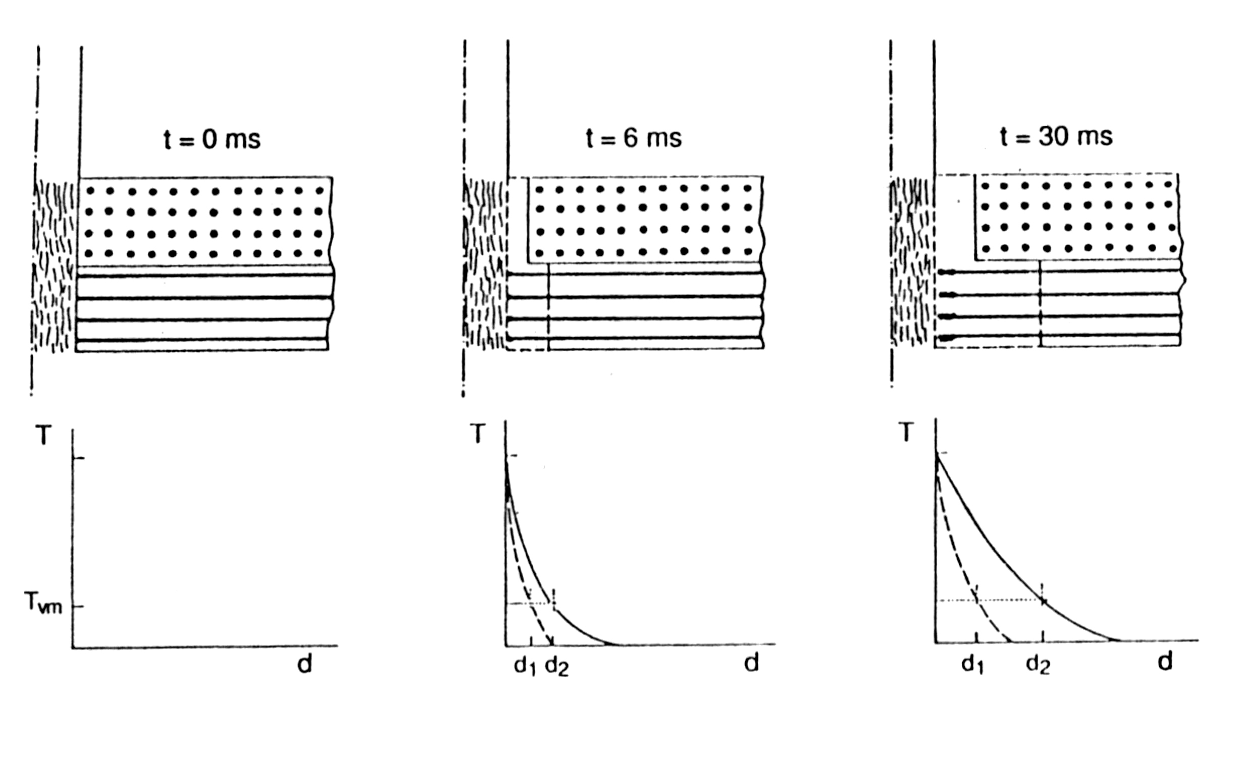
The expected advantages of lasers depend on the thermal nature of the machining process, which does not involve any mechanical force applied to the material. Nevertheless, some difficulties arise because of the difference in the thermal properties of fibre and matrix. The effects of the laser beam on a material are generally connected with the following characteristics of the beam and material properties: power density, wavelength of emission, interaction time, polarization of the beam, absorption coefficient at the given wavelength, melting and vaporization temperature, thermal conductivity and heat capacity. FRPs(Fiber reinforced plastics) generally exhibit a high absorption of infrared rays typical of those produced by CO2 laser. Moreover, their thermal properties are such that the vaporization process occurs at much lower specific powers (103-105 W/cm2) than it does in metals. The thermal degradation mechanism leading to material removal is strongly influenced by the nature of the constituent materials (fibres and matrix). The thermal properties of various polymeric resins, which constitute 40-60% by volume of an FRP, are similar to each other. They are characterized by low values of thermal conductivity, thermal diffusivity, and, decomposition heat. Differences of thermal properties between fibres and matrix are extremely high for both graphite and glass fibres while such differences are low for aramid fibres. The energy needed for the vaporization of the fibres is higher than that required for the matrix; hence the laser power required for cutting FRP will be strongly dependent upon the kind of fibres and their volume fraction. At high specific powers the time to vaporize the FRP constituents is very short but, due to their different thermal properties, fibres and matrix can exhibit very different values of vaporization times. It is possible to observe two limit conditions under constant specific power: both fibers and matrix exhibit slightly different vaporization times as in the case of polyester resin and aramid fibres and therefore the composite behaviour can be considered homogeneous; when fibres and matrix show very different vaporization times (graphite-resin and glass-resin), the resin reaches its vaporization temperature while the fibres are still unaffected. It was shown that heat penetration into the laminae and extension of the heat-affected zone are larger by almost an order of magnitude for CFRPs due to the high conductivity of fibres (Tagliaferri, V. et al.1985). For 0/90 laminates the thermal degradation is depicted in Figure 4 as a function of the interaction time: this is the time that the laser beam illuminates a zone of material, and is calculated as the laser beam diameter to the feed rate ratio.
Fig. 4 Scheme of thermal degradation for 0/90 laminates as a function of interaction time (Tagliaferri, V. et al. 1987)
- Introduction to application in laser machining of composites
Drilling: Due to their light weight, high strength, and directional properties, composites have a great potential for use in manufacturing applications dAlthough in most applications. Composites are cured in a mold to a "near final shape," machining is still required at both the preparing and finishing stages. A finishing process is usually necessary to achieve the final surface quality and dimensional accuracy if the required tolerances are high and cannot be achieved through the initial processing of the composite part. Finishing or secondary processes usually include deburring, trimming, drilling and boring. For deburring and trinurting a typical accuracy to be achieved is ±1mm; while for drilling and boring operations, accuracies of less than ±0.1mm are required. Conventional machining operations are difficult to perform on composite materials due to their anisotropy, inhornogeneous composition, hardness, and abrasiveness. Delamination, debonding, and fiber breakage can lead to strength reduction for the finished part. Excessive tool wear significantly increases the machining time and expense. Laser machining offers the advantages of high machining rates, no tool wear, no contact forces, and relative high precision. The effectiveness of laser machining depends primarily on the thermal properties of the material; the type and amount of constituent fiber and matrix materials determine the thermal response of the composite material to the laser beam. For most composites, mechanical machining techniques create excessive heat buildup and shear forces at the cutting zone, causing delamination between composite layers and debonding between fiber and matrix. Laser drilling was also conducted on several ceramic matrix composites. Silicon nitride and alumina matrix materials with imbedded zirconia were drilled with a 1200W beam to produce mounting holes for the manufacture of tool inserts.
Cutting: Although laser systems usually have a high capital cost, laser cutting has the advantages of a narrow kerf width, localized material damage, and high cutting speeds. For aramid-fiber materials, laser machining rates of 2.5 times mechanical cutting speeds can be achieved . Several recent investigations have been performed on laser cutting and drilling operations for fiber-reinforced polymers. Cutting on glass/polyester, graphite/polyester and aramid/polyester materials was performed for material thicknesses ranging from 2.0mm for graphite/polyester to 4.5mm for Kevlar/polyester. Laser power ranged from 300W to 2kW. A coaxial Helium gas jet was used. Laser scanning velocities varied from 0.5 to 3.5m/min. Using a 1kW CW beam and scanning velocities in the range of 17 to 34mm/s, through-cutting was performed on Kevlir/epoxy workpieces with thicknesses up to 9.5mm .The use of a pulsed beam significantly improved the cutting speed for glass-fiber materials (Konig W. et al. 1985). One characteristic of laser cutting is the relation between cutting efficiency and beam scanning direction relative to fiber orientation. Due to material anisotropy, the thermal response of a workpiece to the laser beam depends on cutting direction. This effect is most apparent in graphite-fiber composites, where the thermal properties between the constituent materials are very different. In cutting experiments on a uniaxial laminate (Flaum, M and T. Karlsson 1987), heat losses were found to be maximum and cutting speed were minimal when the fibers were orthogonal to the cutting direction; in this orientation, the heat flux is along the fiber direction.
Cutting quality, in terms of presence of charred material, extension of delamination, and slope of the kerf surface, depend on the scanning velocity, laser power, and the assist gas. A coaxial inert gas jet (He and Ar) can be used in the cutting process to minimize charring. In general, the cutting quality is highest for composites which exhibited similar thermal properties between constituent materials (such as Kevlar/polyester). Graphite and glass-fiber materials yield poorer results due to the high fiber vaporization temperatures and the high thermal conductivity of graphite. Graphite-reinforced composites are found to be less suitable for laser cutting due to high fiber conductivity and vaporization temperature. Two modes of damage were found for the cutting process. (1) Surface damage due to heat conduction effects (primary damage mode) was found to exist near the beam entrance region of the kerf. (2) Surface damage due to reflected assist gas (secondary damage mode) occurred mainly near the beam exit region. In laser cutting experiments performed on graphite/epoxy, the heat-affected zone at the kerf entrance was found to be significantly higher than at the kerf exit.
The experiments results available in the literature (Konig, W., et al., 1985) support the usefulness of laser technology in cutting Glass Fibre Reinforced Plastics (GFRP), Aramid Fibre Reinforced Plastics (AFRP) Carbon Fibre Reinforced Plastics (CFRP).
(a)
(b)
(c)
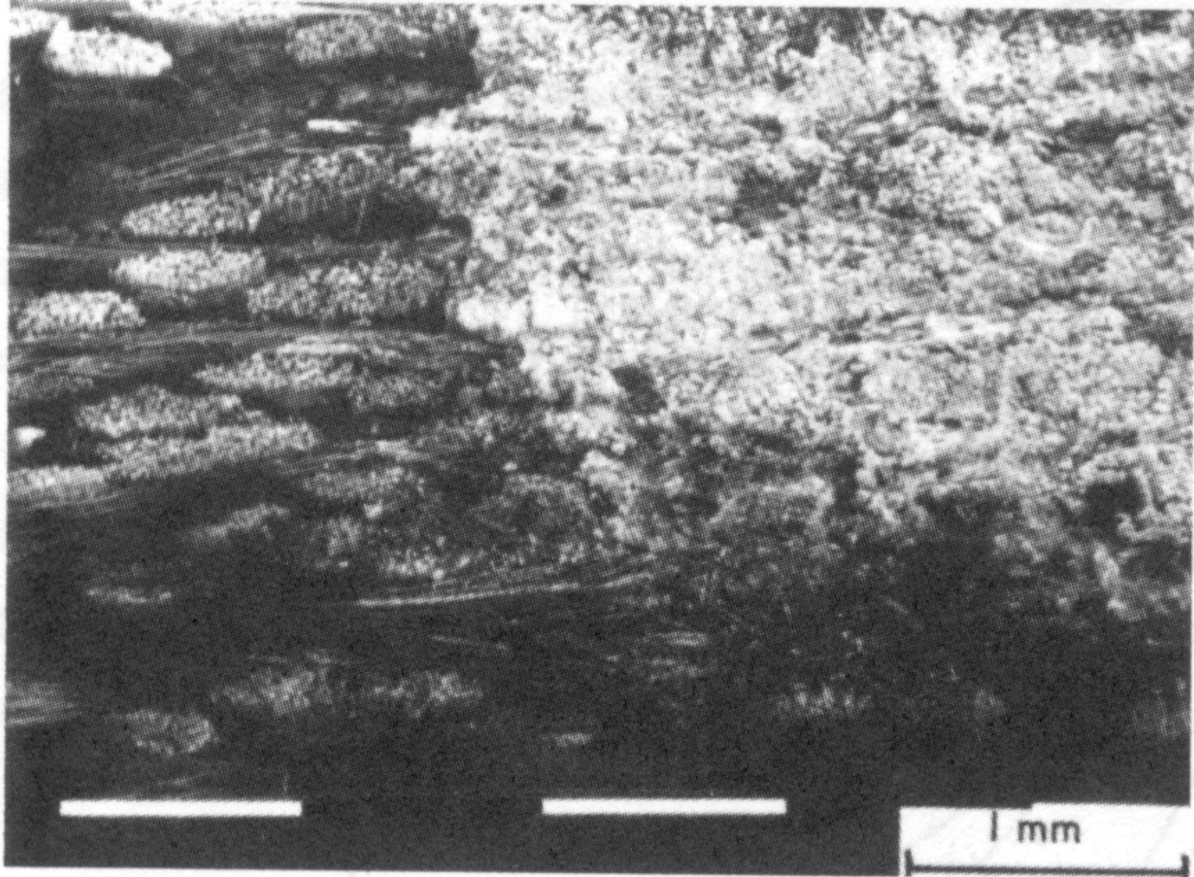
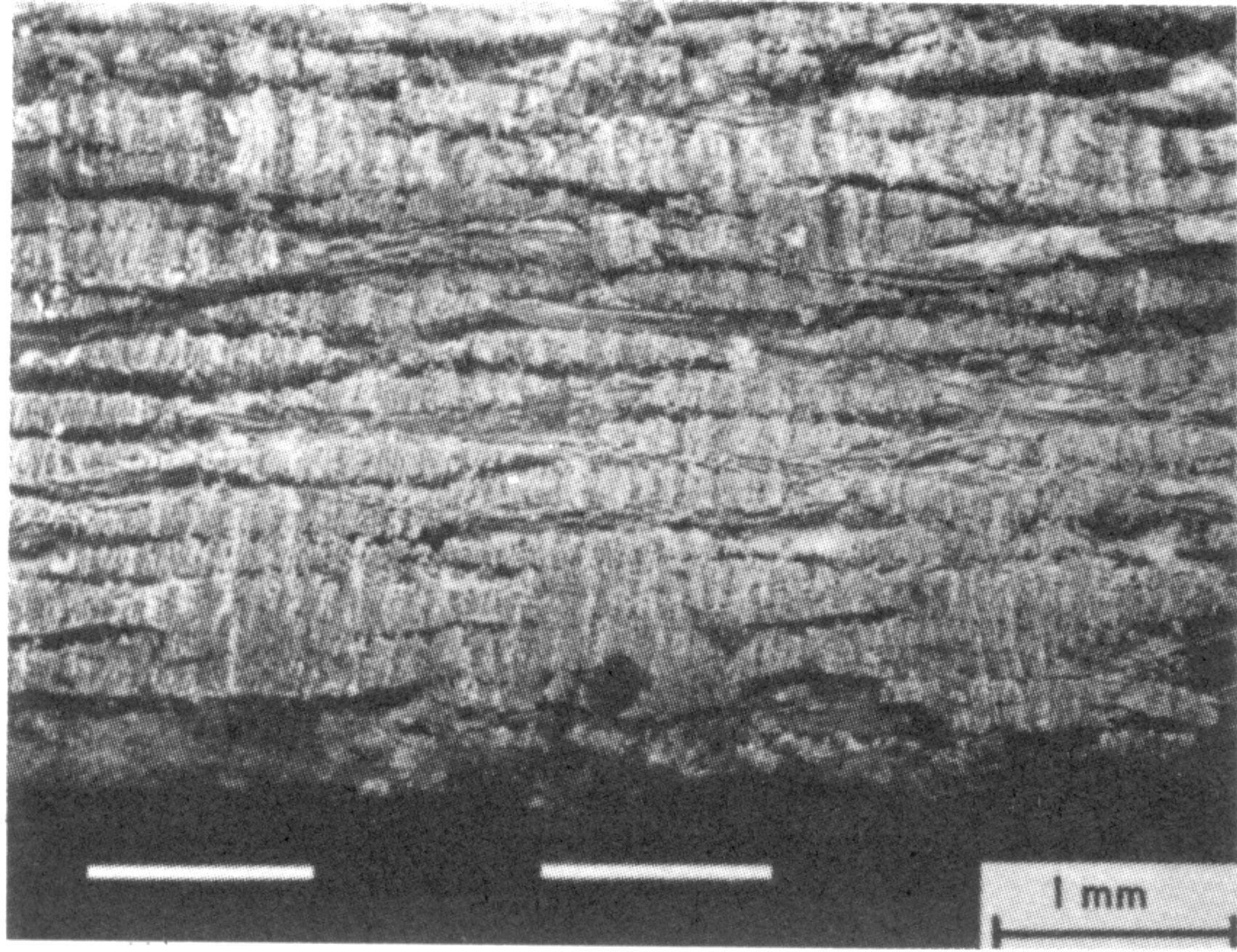
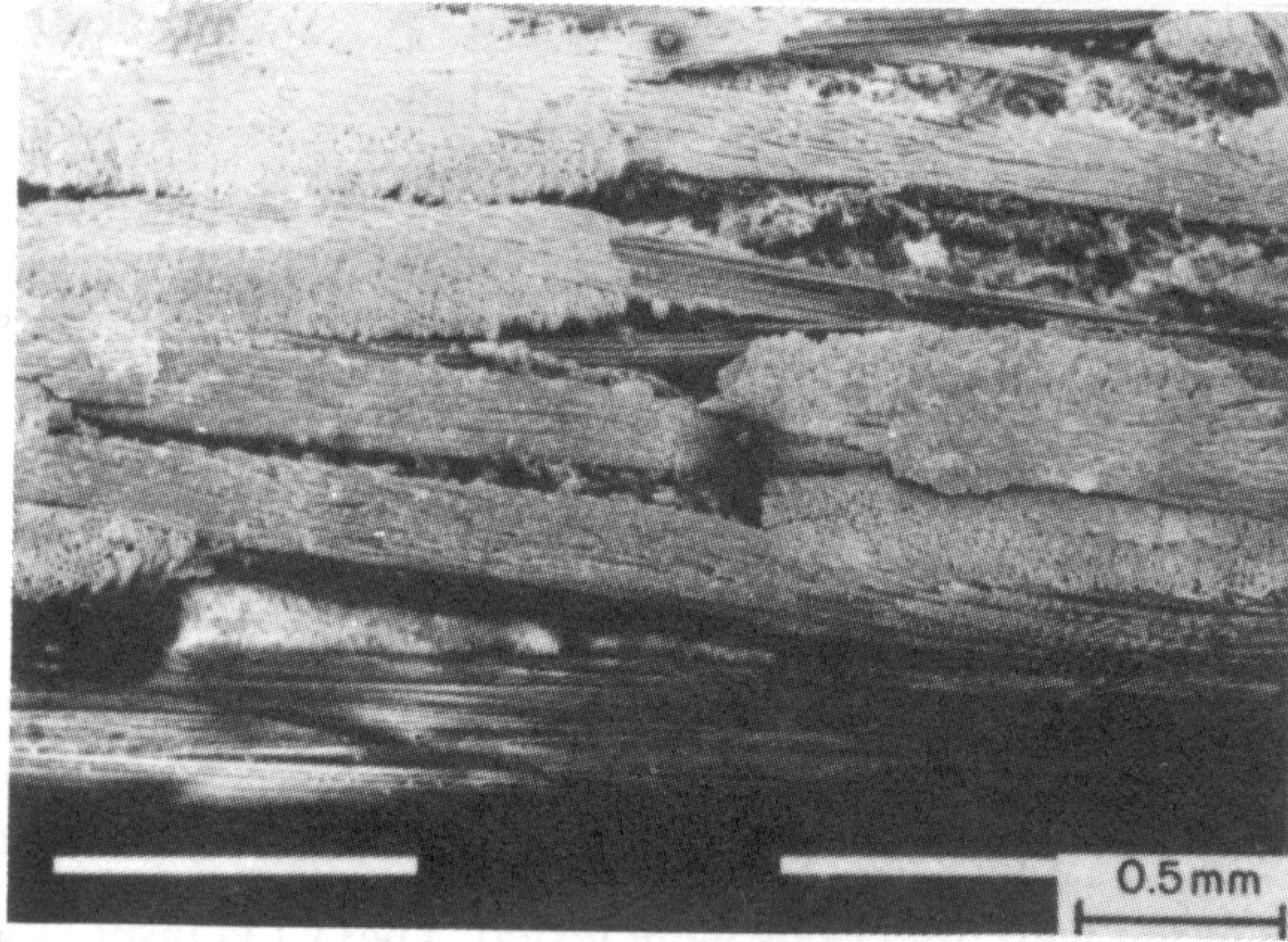
Fig. 5 (a) SEM micrograph of CFRP cut surface abtained at 0.5m/min (b) SEM micrograph of GFRP cut surface abtained at 0.5m/min, and (c) SEM micrograph of AFRP cut surface abtained at 1m/min (Konig, W., et al., 1985)
A typical cut edge obtained at 0.5 m/min is shown in Fig. 5(a). The matrix loss between laminae is much higher than that observed for the other materials; however, warp fibres appear to be cut at the same length. The bottoms of the cavities are smooth and free from any burnt material. Micrographic observations show that for a given laser power, the morphology of the cut edge is strongly influenced by the cutting speed. Fig. 5(b) shows the cut edge obtained at 0.5 m/min: the burnt layer resulting from the cut is visible on the right while the lower zone is shown on the left of the figure. The latter appears to be very irregular, a remarkable loss of matrix being evident while the fibres do not show a clean cut. At cutting speeds > 0.5 m/min no evident improvement was observed. Scanning electron micrograph of a cut surface is shown in Fig.5(c) Macroscopic grooving is visible. The striations lie almost parallel to the cutting direction and seem to be more pronounced at the entry zone of the beam. The surface appears uneven due to loss of material, particularly in the longitudinal direction, i.e. parallel to the laminae and this seems to be greater at the entry zone of the beam. The longitudinal shape of the removed material as well as the scanty presence of longitudinal fibres suggest that many fibres in the weft direction were removed together with the resin. The fibres in the warp direction do not show a clean cut but rather a carbonized end. On the other hand, the bottom of the longitudinal grooves appears to be smooth and free from any carbonized residues.
Nonuniform material loss appeared to be a function of the matrix and fiber materials selected (aramid versus glass and graphite materials) and depends strongly on the thermal conductivity of the constituent materials. Aramid fibers have thermal characteristics similar to polymer matrix materials, so material behavior during bearn/material interaction is similar to that of homogeneous materials. SEM micrographs of the kerf surface for aramid/epoxy shows a relatively smooth surface between fiber and matrix regions. Graphite fibers, however, exhibit thermal conductivity values which are up to two orders of magnitude higher than polymer matrix materials. This leads to highly directional heat conduction in the workpiece and a much larger thermal damage zone than with other fiber materials. Also, the thermal damage zone tends to propagate along the direction of f-ber orientation. Glass fibers can be removed through melting, instead of vaporization. This phenomenon can lead to increased surface roughness, or irregularities in fiber tip lengths, due to the presence of resolidified molten material.
One problem in laser machining of composite materials is that the products of chemical decomposition produced under elevated temperatures can be hazardous. Mass spectrometry and gas chromatography analysis were conducted on gas samples during laser cutting of graphite/epoxy, araniid/epoxy and glass/epoxy (Flaum, M and T. Karlsson 1987). Most particulate products were fragmented powders of fiber materials. Matrix decomposition yielded concentrations of CO, CO2 and low molecular organic compounds. It has been shown that cutting of ararnid/epoxy produces large quantities of hydrogen cyanide, which may pose a considerable health risk.
- Scribing: The laser grooving or scribing process for carbon/teflon, glass/teflon and glass/polyester materials were investigated (Chryssolouris, G., P. Sheng, and W.C.Choi, 1988). The major issue in laser scribing of composites is the anisotropic nature of the material. The groove depth, groove shape, and heat-affected zone will vary depending on the laser beam direction relative to fiber orientation. This effect is apparent for long- fiber composites where the fibers, with different thermal properties than the matrix, are oriented in specific directions within the matrix. In most grooving applications, the laser beam is directed perpendicular to fiber orientation since fibers are usually aligned in the plane perpendicular to the workpiece thickness; however, in some cases such as laser turning or threading, the laser beam can be directed at an arbitrary angle relative to fiber orientation. Heat losses to the environment and matrix decomposition have the effect of groove depth reduction particularly at high energy densities.
For introduction to laser machining of advanced composites systems, please see Level 2. Section 5.2
![]()
![]()
![]()