![]()
![]()
Section 4.2 Improve Machining Quality through Monitoring and Modulation of Laser Beam
Currently the most common industrial laser processing is laser machining, a process which lends itself to system automation. A necessary part of a fully automated system is process monitoring and feedback. Then with proper modulation of the laser beam, machining quality can be improved. In this section, laser focus control is discussed, then, some progress in laser percussion drilling and high quality hole drilling are introduced.
4.2.1 Laser Focus Control in Laser Machining
An increasing demand for quality assurance in manufacturing and also in laser processing requires to check the laser beam-the central tool in laser machining processes. With the ISO/DIS 11146 there is for the first time a standard for laser beam characterization. The basic parameters o describe a laser beam are:
Laser power and pulse energy can be measured by power meters, the measurement is done reliably by thermopile or by calorimetric devices. There are also a lot of methods and devices to measure the beam position, dimension and beam propagation factors, but most of the devices does not allow measurement in full power. Measuring devices for high power lasers in industrial environment has been studied which can run at full power (several kilowatts) even in the focus with power densities from more than 108W/cm2 [H. Schwede, et al., 1998].
Errors in laser machining may be caused by any of the following reasons. The gas pressure may be set up incorrectly, the laser power or thickness of the material being cut may vary, errors may also arise from defocusing due to poor fit-up, or limitations in robot maneuverability. There are particularly issues with the emerging 3D cutting applications. An ideal sensing system should be able to monitor and discriminate between all of these possible errors, rather than the currently available sensors which can only monitor or control individual parameters. However, such monitoring systems are difficult to realize. Among these factors, focus control is always important in any laser-related applications.
There have developed many methods for laser focus control. Focus control can be realized by monitoring the capacitance between the workpiece and the nozzle[S. Berrmann, et al., 1992]. This is an established technique but its limitations has to be reminded. The shape of the workpiece as well as damage to the nozzle can change the capacitance, thus giving incorrect focal measurement. Furthermore, the system does not work with a non-conductive workpiece.
Two other methods are beam control through physical contact and optical triangulation. Physical contact methods may use some sort of roller or lever attached to the nozzle, which detects the surface. For the triangulation methods, a 'stripe' of light from a laser diode is scattered from the surface of the workpiece and monitored with a detector array. Knowing the distance between the emitter and receiver, all that is needed to calculate the distance to the workpiece is the angle of incidence of the light. These methods works well for flat plates but give incorrect messages for non-flat surfaces.
Focus control in laser machining making use of acoustic signals has also been studied, but proved to not very successful [M.D.T. Fox, 1998]. Another technique is being developed which makes use of the online thermographic system[H. Haferkamp, et al., 1998].
An ideal focus control system should have high spatial resolution and can operate in real time, these two factors are even more important when high quality and short laser pulse are involved. One potential technique to reach this aim is the on-axis monitoring system making use of the light generated at the workpiece [M.D.T. Fox, 1998].
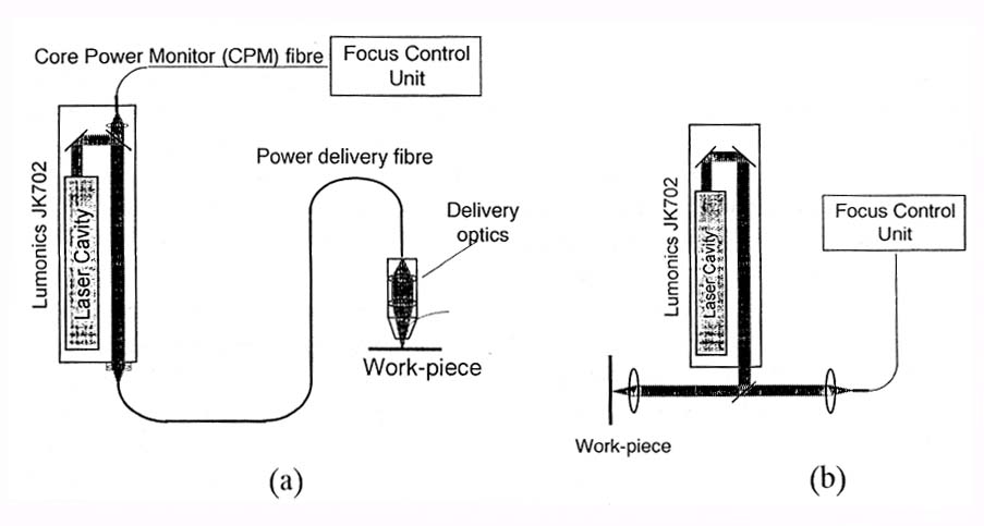
Figure 4: Laser beam focus control system for (a) fiber optic delivery, and (b) direct beam delivery[M.D.T. Fox, 1998].
A schematic of the optical sensor system is shown in figure 4. The high powered laser light is delivered through an optical fiber and imaged onto the workpiece by the delivery optics. Broadband light is generated by the heating up of the workpiece, and part of the light is collected by the same delivery optics and imaged onto the output end of the delivery fiber where it will counter-propagate back along the fiber and into the laser head. This light can then be coupled into a second fiber from behind one of the turning mirrors in the laser head, filtered as required and then imaged onto a detector. The chromatic aberrations of the delivery optics are used in order to detect focal errors.
The basic principle is as follows. If the lenses are achromats, all light would be imaged on the fiber. But since the lenses are not achromatic, the focal position will vary according to the wavelength. Thus the near infra-red radiation and the visible radiation has different focal positions. The magnitude difference of the infra-red radiation and the visible radiation serves as error signal for focus control. When the workpiece is at the focus of the laser system, the sensor system is adjusted to have equal magnitude for the infra-red radiation and visible radiation. When the workpiece deviates from the focal location, the error signal is non-zero, and has different sign if the deviations are different in direction. The reason is that if the workpiece is too far away from the laser output lens, the near infra-red light is coupled into the sensor more efficiently than the visible, and vise versa. This error signal can be used in closed loop feedback via a servo-driven delivery lens-housing, to allow immediate correction of the error.
For the fiber delivery case, the return path for the optical signal is simply the reverse of the delivery route, so the image of the melt-pool will always be correctly centered on the delivery fiber. With conventional optics beam delivery however, careful alignment is necessary. Also selection of lenses with high chromatic aberrations can help to ensure that the focal positions have a reasonable separation at the monitor fiber.
This system of focus is non-intrusive, it is also on-axis, so it is convenient in industrial life. The error signal reflects the real time focus change at the machining position, with the help of high speed data acquisition, data analysis and feedback control systems, high spatial resolution, real time on-line control is possible. At high intensities, plasma phenomena may complicate the sensor signal, but the focus control can be carried out before actual machining process--use a low power level first.
It has limitations, though. The reliability of the error signal depends on the achromatic aberration of the optics, thus accurate calibration is needed before accurate control can be realized. As any optical method, the reliability of the signal is also influenced by the surface impurities. But since this system can be realized nearly real time and is non-intrusive and compact, it has the potential of applications in 3D laser cutting and welding.
The above mentioned focus control is used in percussion drilling. But besides focus control, other methods of laser beam modulation are being developed to improve the quality of percussion drilling.
4.2.2 Beam Modulation Related Quality Improvements in Laser Drilling
Laser drilling is one of the oldest applications of laser machining processes. A well-known example of laser drilling is the drilling of airfoil cooling holes in components of aircraft engines. Another application is drilling holes for fuel filters for automobile manufacturing. Yet many issues remain to be solved when high quality holes are to be drilled in various materials:
Usually Nd:YAG lasers with pulse length of several tenth of milliseconds are used to drill such holes when a certain degree of inaccuracy of diameter and shape as well s thin recast layer can be tolerated. In cases when higher accuracy is required, laser drilling with millisecond pulses could not meet the requirements, however.
Means to increase precision include reduction of pulse length and improve machining techniques.
Laser intensity distribution has influence on the shape of the hole of course, but there are other factors such as the changing profile of the hole, the variation of material properties, etc. So different material may have different hole profiles even if same laser condition is used. In laser drilling, material is removed as a mixture of melt and vapor, the distribution of which depends on material properties and laser intensity: A large amount of melt is advantageous for process efficiency, but is a source of destabilization, on the other hand. The thicker the layer of melt, the less is defined its surface geometry, the more reshaping effect of the hole geometry fluctuates. The thickness of a layer molten during a laser pulse can be approximated as:
L=2 *(a *tp)1/2
where L is molten layer thickness, a is the thermal diffusivity, tp is pulse duration (>10ps to be valid).
The expectation to increase drilling accuracy by simply shortening the pulse duration in laser percussion drilling was not satisfactory, however. Percussion drilling of 1 mm thick steel with a nanosecond laser generate massive recast layers. Further reduction to femtosecond range, melt could be avoided, but the shape of the cross section is far from cylindrical, as seen in figure 5.
For this reason, the reduction of pulse duration had to be accompanied by the development of adequate techniques.
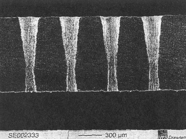
Figure 5: Holes obtained by percussion drilling with fs-pulses result in poor hole cross sections [Friedrich Dausinger, 2000]
Figure 6 illustrates various drilling techniques, Single pulse drilling, Percussion drilling, Trepanning and Helical Drilling. Trepanning is the standard technique for large holes, e.g. 500 micron holes in turbine blades. It is essentially a percussion drilling process followed by a cutting procedure. The application of nanosecond pulses to trepanning can increase the quality of the hole. But the drawbacks of percussion drilling remains.
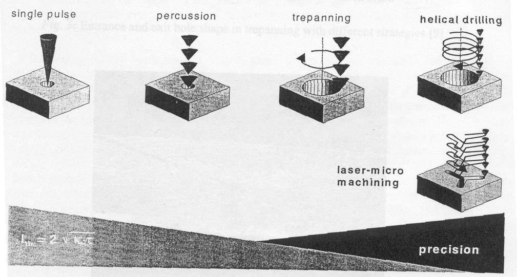
Figure 6: Various techniques in laser drilling [Friedrich Dausinger, 2000]
A new technique, called Helical Drilling, makes use of the breaking up of the process into a multitude of ablation steps in order to enhance the accuracy. In contrast to trepanning, the helical drilling reaches the breakthrough only after many turns of spiral describing the path of the ablation front.
Helical drilling has the following favorable effects on drilling accuracy:
Figure 7 shows a figure of a micro hole in 1mm thick steel plate by helical drilling using Nd:YAG laser with 10ns laser pulses. The cross section shows high cylindricity, no visible recast layer and sharp entrance and exit edges.
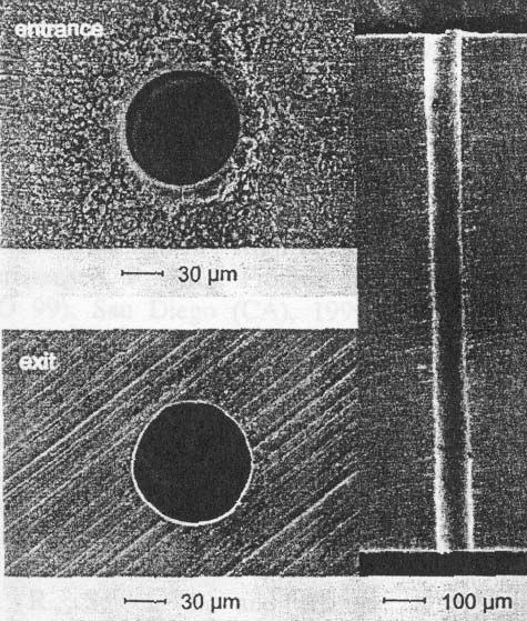
Figure 7 Micro hole in 1mm thick steel plate by helical drilling using Nd:YAG laser with 10ns laser pulses
(Friedrich Dausinger, 2000)
The beam path is not limited to circular geometry. With suitable optical systems like scanners or by movement of the workpiece, any shape can be formed. This means helical drilling can be applied to laser micro-machining when high accuracy and high machining quality is required. Helical drilling is a technique that is efficient when the helical diameter is close to the focal diameter of the laser beam.
Trepanning and helical drilling is much more cost expensive and time consuming than percussion drilling. Researchers and manufacturers are seeking new ways to optimize the process, with particular focus on achieving better quality holes while keeping the drilling speed high at economical costs.
Laser percussion drilling is usually accompanied with spatter and taper. The spatter and taper is undesirable especially for applications such as effusion cooling holes in turbine engines, where the flow and efficiency of the cooling air is crucially dependent on the surface quality and geometry of the holes. The removal of spatter is a challenging and irreversible process, and taper can not be easily eliminated. It was reported that a specially developed anti-spatter composite coating (ASCC) could greatly reduce the spatter in percussion drilling. When this is combined with Sequential Pulse Delivery Pattern Control (SPDPC), the taper of the hole can also be reduced or avoided [D. K. Y. Low, et al., 2000, 1999].
Sequential Pulse Delivery Pattern Control (SPDPC) is a method of varying the parameters of individual laser pulses within a pulse train needed to perform a laser material processing operation[D. K. Y. Low, et al., 1999]. In laser percussion drilling, hole taper control can be achieved by linearly increasing the laser pulse energy by linearly increasing the laser power throughout a pulse train as shown in figure 8. In contrast, normal percussion drilling use the same pulse parameters repeatedly throughout the drilling train of pulses.
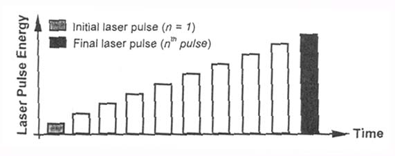
Figure 8 Schematic diagram of the linearly increasing SPDPC method(D. K. Y. Low, et al., 1999)
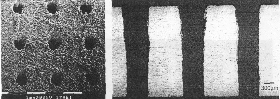
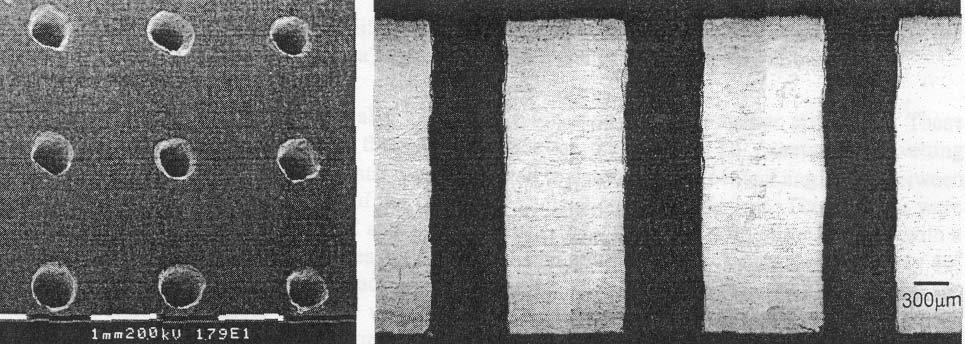
Figure 9(b) shows typical micrographs of spatter free and taper free laser percussion drilled holes produced by combined use of anti-spatter coating and Sequential Pulse Delivery Pattern Control (SPDPC). In comparison the upper figure shows strong spatter and taper when normal percussion drilling was used.
(a)
(b)
Figure 9 Typical micrographs of (a) normal percussion drilled holes showing strong spatter and taper, and (b) spatter free and taper free laser percussion drilled holes produced by combined use of anti-spatter coating and Sequential Pulse Delivery Pattern Control (SPDPC).
(D. K. Y. Low, et al., 2000)
The finite hole taper is a common feature found in holes percussion drilled using normal pulses. The reduced taper in SPDPC can be explained as following.
First, the material removal in laser drilling with intensities in the range of 105-108W/cm2 has strong liquid melt ejection. As a result of surface vaporization a recoil force is generated in the opposite direction such that the liquid melt is pushed out of the interaction zone towards the hole entrance. This hot flowing melt can further induce melting of additional solid material on the hole wall during laser drilling, or on the side of the weld track or cut kerf in the case of laser welding or laser cutting. The interaction time between the melt and the hole wall was the greatest at the entrance side of the hole and reduced with depth. Due to this variation in hole wall erosion throughout the hole path, a hole taper is formed with the entrance end being enlarged.
Secondly, owing tot he fact that the laser peak power in normal percussion drilling was identical, the laser pulse intensity would subsequently be reduced with hole propagation. This is due to the increasing beam diameter with beam divergence along the laser axis and the absorption of any part of the incident beam at the upper section of the hole. Reduced laser intensity results in reduced diameters.
Finally the taper is also related to the non-uniform spatial distribution of the laser intensity.
By using the linearly increasing SPDC, it was found that the fraction of upward melt ejection before breakthrough was significantly reduced from 80% to 60%. After occurrence of breakthrough, most f the material was ejected downward out of the hole exit. The linearly increasing power helps compensate the diameter difference of the entrance and exit diameter.
This points out a way to completely eliminate taper problem in laser drilling. The modulation of laser intensity can be realized by software and the laser controlling unit, thus no extra hardware is needed.
In summary, we have discussed some progress in monitor and modulation of laser beam in order to improve the laser machining processes. They can divided into focus control, magnitude modulation, pulse duration improvement and frequency modulation. Shorter wavelengths can generate better accuracy than longer wavelengths, for example from 1.06 micron to 532 micron light or even to UV light and deep UV light. However, the modulation of laser wavelength is not widely studied yet due to the difficult in changing the laser wavelength. It is interesting to refer to the introduction part of this project, where we discussed the features of laser energy.
References:
Friedrich Dausinger, 2000, "Drilling of High Quality Micro Holes," ICALEO'2000, Section B pp. 1-10.
D. K. Y. Low, et al., 2000, "Combined Spatter and Hole Taper Control of Nd:YAG Laser Purcussion Drilling," ICALEO'2000, Section B pp. 11-20.
D. K. Y. Low, et al., 1999, "Taper Control During Laser Purcussion Drilling of NIMONIC Alloy Using Sequential Pulse Delivery Pattern Control (SPDPC)," ICALEO'1999, Section C pp. 11-20.
H. Haferkamp, et al., 1998, "Online Quality Monitoring During Laser Beam Cutting Using a Thermographic System," ICALEO'1998, Section C pp. 11-17.
M. D. T. Fox et al., 1999, " Optical focus control for laser percussion drilling," ICALEO'1999, Section C pp. 1-10.
M. D. T. Fox et al., 1999, "Applications of Optical Sensing for Laser Cutting," ICALEO'1999, Section C pp. 106-114.
S. Berrmann, et al., 1992, "Capacitive Clearances Sensor System for High Quality Nd:YAG Laser Cutting and Welding of Sheet Metals," Euroean Conf. on Laser Treatment of Materials (Gottingen, Germany), pp. 51-55.
H. Schwede, et al., 1998, "High Performance Laser Disgonostics in Industrial Environment," ICALEO'1998, Section A pp. 112-121.
![]()
![]()