![]()
![]()
As stated in Chapter 1: Introduction of Laser Machining Processes, three flows exist in any manufacturing processes, they are Information flow (I), Energy flow (E) and Mass/Material flow (M). In this chapter, we will discuss Laser Machining System and Control. Information flow is conveyed through the control of systems. Human beings issue the commands, these commands are realized through control of the laser machining systems.
The design information can be in CAD file format. To manufacture the final parts through a laser machining system, these information should be transformed to the controlling command to fire the laser, adjust the laser power and frequency, and to coordinate the motion of the XYZ stage. Practical industrial laser machining systems have integrated the motion control and laser control system to automate the machining process. Usually control boards and industrial computers are used for this purpose, special software can transform manufacturing information into the control command of laser parameters, optical transmission and working stage motion. Figure 1 shows a five axis workstation combining laser/workpiece motion.
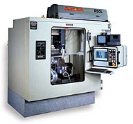
Figure 1: Five-axis workstation combining laser/workpiece motion (Courtesy of Convergent Energy)
Two kinds of controller are commonly used in laser machining. The first is Open Loop Controller. For example, to realize the desired trajectory in laser cutting, laser beam is focused on the moving working stage without feedback. On the other hand, Closed Loop Controllers use the signals from sensing or monitoring elements as feedback to reduce the control error. There are other control schemes such as Adaptive Control, Intelligent Control, Robust Control, etc. Automation of the laser machining system is important for the purpose of improving efficiency and machining quality.
Rather than go into details of the hardware of laser machining systems, which can be found in relative books[Steen, 1998; Ready, 1997; Eloy, 1985] and manuals, we will move onto the discussion of some new trends in laser machining systems.
S4.1 Laser Beam Delivery Through Optical Fibers and Waveguides
Laser beams travel in straight lines, conventionally mirrors and prisms are used to change the direction of propagation. Other optical elements can shape the beam or split it into multiple beams as required. Most of today's solid state lasers use a fiber beam delivery system, which provide a safe and flexible beam delivery path to the workpiece. Such beam delivery systems can be automated by computers or combined with robot technology[Cunningham, 1990].
The propagation of laser light in fibers depend on Total Internal Reflection[Diament, 1986]. The core layer of the fiber has a larger refractive index than the outer cladding layer, ideally 100% of the incident laser energy is reflected up and down and is trapped inside the core under two assumptions. First, the laser incident on the fiber above a critical angle to allow total internal reflection, otherwise part of the light is reflected and part is transmitted, which means lower efficiency and is not desirable. Another assumption is that the core is lossless, which mens it doesn't absorb any energy as light is transmitting inside it. Unfortunately any material absorb a portion light energy or attenuate the light as light propagates, although modern optical fiber has a energy loss as small as 4dB/Km.
When we talk about absorption, we must keep in mind that the absorption of a material is strongly related to the wavelength. For practical fibers, the core material has low absorption for the 1.06 micron Nd:YAG laser, but the absorption is much higher at 10.6 micron (CO2 laser) or at UV wavelength. Higher absorption means hiher percentage of the laser light being transformed into thermal energy. This is the reason why normally only Nd:YAG laser is supplied with the ability of beam delivery with fibers. Laser beam delivery through fibers first found application in telcommunications, which only use very small energy levels. In telecommunication, the major concern is whether information can be transmitted without distortion and at high speed. In laser machining, however, the major concern is that whether sufficient high power can transmitted to the workpiece with high beam quality.
Since laser material processing requires very high irradiance, from 103 to 109 W/cm2 at up to 10 killowatts of average power, the coupling of high power lasers into multimode fibers becomes an important issue. To get high beam quality from the output of the fiber, however, single-mode fibers could be the solution as discussed below.
Nd:YAG laser beam delivery through single-mode optical fibers for micromachining applications:
High precision material removal is needed in all micro-machining applications. Excimer lasers are widely used for this purpose. Excimer process is generally ablative, and relies on the short laser wavelength. Although highly-precise, it allows only a limited depth of material (1-10 microns) to be removed per pulse. Nd:YAG processing is generally thermal and allows removal depths of a couple of hundred microns with a single pulse. When a high beam quality is used, this process can provide sufficient precision and feature size for many applications. Nd:YAG laser machining system is more flexible than excimer lasers. An additional benefit of the Nd:YAG system is that light can be delivered to the workpiece through optical fibers. It is often easier and cheaper to process the workpiece by scanning a light-weight delivery fiber and focusing optics across it, rather than moving either the workpiece or the laser itself.
The high brightness and high beam quality required for micro-machining has precluded the use of the large-core optical fiber beam delivery systems currently available. For precision processing, a high beam quality, M2 <3, is required, so a small-core diameter must be used. But even with small core diameters (50 microns), the output intensity profile can be significantly modulated due to the strong interference between the modes excited in the fiber, beam quality deteriorates, which can adversely affect the process.
One solution is to use a fiber with a sufficiently small core diameter that only the dominant mode can propagate. In this way, all intermodal interference problems can be avoided.
Numerical Aperture (NA) measures the difference between the core refractive index (n1) and the cladding refractive index (n2):
![]()
The number of mode that can propagate in the fiber is:
![]()
where a is the core diameter of the fiber, l is wavelength [Senior, 1985].
Thus for l =1.06 microns, to make N=1, core diameter must be small enough (~7microns). Such a fiber is called a single-mode fiber, and is the standard type used for high-bandwidth telecommunications applications.
Coupling light from an industrial Nd:YAG system into a single-mode fiber poses practical problems. Only part of the laser energy is coupled into the core of the fiber, the remainder of the laser energy is coupled into the fiber cladding, which can lead to thermal damage at the point where the cladding modes are removed. Even for M2=1, only 70% of laser energy is coupled into the core.
In any practical situation, the cladding of a glass optical fiber is covered by a protective buffer layer. With small-core fibers, this buffer material is designed to have suitable refractive index to "strip off" the light in cladding by preventing them from being guided by reflecting at the buffer-cladding interface, which could seriously degrade the beam quality. The buffer absorbs and scatters this light. Hence when cladding light encounters the buffer material, power is absorbed. Absorbed Power levels higher than 1W will be sufficient to damage the fiber cable. Therefore special cladding-mode strippers should be devised to remove this light from the cladding whilst avoiding excessive heating. The maximum power which can be transmitted is ultimately limited by the non-linear optical effects in the fiber, such as Brillouin scatter. Non-thermal damage has also been observed when coupling Q-switched Nd:YAG laser light into larger fibers[Allison, 1985], arising from self-focusing effect.
The standard technique used to remove light in cladding is to coat the fiber with a buffer material, such as acrylate or poluimide, which has a refractive index slightly greater than that of the cladding. This has the additional advantage of mechanically protecting the fiber. Although such mode-stripping buffers are suitable for low power applications such as telecommunications, the optical power levels used in materials processing results in thermal damage. A successful alternative is to use a "Distributed Absorption Cladding Mode Stripper".
If a reflective material, such as a metal coating, is placed in optical contact with the fiber cladding, it will absorb a small percentage of the cladding light on each reflection. This will therefore distribute the thermal energy over a larger volume. For example, an aluminum-coated fiber was embedded in a metal block to act as a heat sink. It successfully removed 25W of light from the fiber cladding for several minutes, and could probably form the basis of a reliable and repeatable setup.
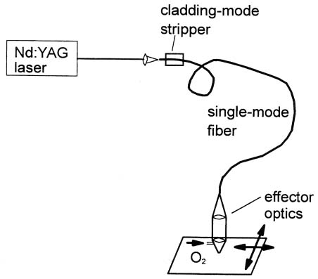
Figure 2: Single-mode fiber laser cutting system (Ducan and Julian, 1997)
Figure 2 shows a single-mode fiber laser cutting system. A moderate power Nd:YAG laser emits laser beam with a low divergence, M2=1.9. This light was coupled into the fiber using an achromatic doublet. A suitable cladding mode stripper as described above was employed to remove light from the fiber cladding. The fiberused has a core diameter of 6.4 m m and numerical aperture of 0.11 rad, which only supports a single mode above 970 nm. The mode diameter at 1.06m m laser light is 7.7m m. Laser parameters were chosen to give maximum peak power, achieved with a pulse width of 0.16ms and 100Hz repetition rate. Peak power of 500-640W and average power of 7-8.5W were reached.
The output beam quality from the fiber is excellent. The fundamental mode has a near-Gaussian profile with an M2~1.1, and there are no intermodal interference problems. Instead, the fiber effectively asts as a spatial filter for the laser, giving a near diffraction-limited output.
The light from the output end of the fiber is collimated with a 80mm focal length achromat lens, and refocused with an identical lens onto the surface of the workpiece to give a spot diameter of about 8m m. A conical nozzle is used to coaxially deliver oxygen assist-gas at a pressure of 6bar. The nozzle/workpiece stand-off was 0.5 mm. With such laser parameters, a maximum cutting speed of 0.24m/min was achieved in 200 m m thick stainless steel sheet. The kerf width was about 110 m m, as shown in figure 3. For the 50 micron thick stainless steel sheet, at repetition rate of 198Hz, pulse width 0.3ms, average fiber output power 3W, the kerf width is 30 microns and the cutting speed was up to 0.45m/min. This demonstrates the capability of the single-mode fiber to deliver realistic power levels for micro-machining.
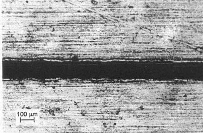
Figure 3: Micrograph of slot cu in 200 micron thick stainless steel woth pulsed laser beam transmitted through a single-mode fiber.
(Ducan and Julian, 1997)
Waveguide for high quality CO2 laser beam delivery:
The wide spread use of fiber optic beam delivery based on fused silica waveguides has significantly increased the operational flexibility and convenience of laser material processing systems and optical detection based on Nd:YAG lasers at wavelength of 1.06 micorns. The additonal flexibility of fiber optic beam delivery gives Ng:YAG laser a considerable practical advantage over longer wavelength lasers (CO2 laser) in high power applications. In recent years, progress has been made in the development of optical waveguides for loner wavelengths (1-11 microns), including glass and single crystal solid core fibers [Worrel and Scarda, 1989; Ikedo, et al., 1986] and glass, ceramic, metallic, single crystal saphire and dielectric-coated metaalic hollow waveguides [Nagaro, et al., 1990; Droor, et al., 1989]. More than 1KW of CO2 laser power has been transferred through hollow waveguides of about 1 m in length[Hongo, et al., 1992]. As the quality and availability of waveguide systems for CO2 lasers improve, more widespread use is expected because of the practical advantages over free space system, which usually involve rather bulky mechanical systems[Su, et al., 1995]. Interested readers can go to the references on this topic for details.
References:
William M. Steen, 1998, Laser Material Processing, 2nd edition, Springer, London, 1998.
John F. Ready, 1997, Industrial Applications of Lasers, 2nd edition, Academic Press, San Diego, 1997.
Jean-Francois Eloy, 1987, Power Lasers, Jogn Wiley & Sons, New York, 1987.
R. Cunningham, 1990, "Delivering Nd:YAG Laser Beams the Easy Way," Laser and Optronics, 9, 59, Sept., 1990
Paul Diament, 1986, Wave Transmission and Fiber Optics, Macmillan Publishing Company, New York.
J. M. Senior, 1985, Optical Fiber Communications: Principle and Practive, Prentice-Hall International Inc., London, 1985.
Ducan P Hand and Julian D C Jones, 1997, "Nd:YAG laser delivery through single mode fibers for micromachining applications," ICALEO 1997, pp. A-91
D. Su, et al., 1995, Optics Communications, 114(1995) 255-261
C. A. Worrel and V. Scarda, 1989, J. Phys. D: Appl. Phys. 22 (1989), 535;
M. Ikedo, et al., 1986, J. Appl. Phys. 60 (1986) 3035
A. Hongo, et al., 1992, Appl. Optics 31 (1992) 5114.
S. W. Allison, et al., (1985), Applied Optics, Vol. 24, pp.3140-3145.