![]()
![]()
S4.3 Monitoring of LMP
Industrial laser machining has been plagued by the problems of reliability. Both in CO2 and Nd:YAG laser machining, this result in unnecessary costs due to the stoppage of production or creation of waste. Monitoring is an important way to inspect the process, give in-time feed back of machining quality. Some aspects of LMP monitoring have been covered in previous section. In this section, we introduce two topics: A monitoring system incorporated in laser heads and the plasma formation observation using nanosecond imaging techniques.
Laser machining has become a well accepted common application in industry and laser processes is more and more involved in automated production systems, so they are expected to function in a more robust and repeatable manner. This increase of reliability and repeatability requirements prompts the development of suitable monitoring systems. Tools must be developed for the online condition monitoring of the process and the machine tool. By obsere certain parameter changes on either the process or the machine tool, quality faults and machine aging could be observed.
Machine faults involving standard peripheral equipment such as positing tables, robots or similar systems is not directly related to the use of laser and is not covered in this discussion. Changes in process parameters such as focal distance, power and speed can directly affect the process quality. Furthermore, the state of the optics, the process gas and beam alignment plays a major role in laser cutting. When considering the source of errors from the laser machine tools, the beam alignment and the optics are critical to the proper functioning of the laser.
It is clear that if sensors wer used to monitor process parameters and machining parameters then the process quality and the state of the laser could be monitored simultaneously. By implementing multi-sensor heads one could collect data relating to the process as well as the state of the laser.
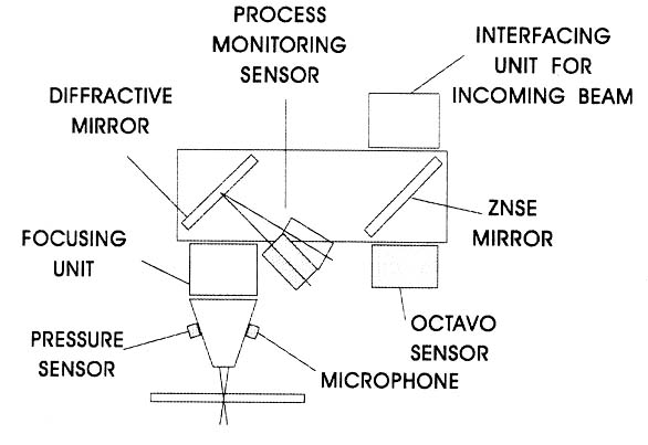
Figure 10: A multi-sensor CO2 laser head [Tonshoff, et al., 1999].
A CO2 cutting head equipped with multi-sensors was shown in Figure 10. A diffractive mirror was used to extract the process radiation. This proved to be a simple way for on-axis process monitoring. On the nozzle end, the microphone as well as a pressure guage is being used. The pressure guage measures the pressure inside the nozzzle. The microphone can either be positioned inside the nozzle or externally to it. The microphone was chosen so that it could withstand high sound pressure levels so that a change from 0-20 bar does not cause any damage.
In CO2 lasers, beam alignment is often a problem. The beam path can be several meters long, in which optical components can deteriorate and shoft the beam before it reaches the workpiece. The 8-quadrant thermopile is critical for finding any misalignments, power losses or beam distortions. The octavo sensor is positioned at the entry of the incoming beam, the use of ZnSe mirror allows a transmission of 1% CO2 radiation to the sensor. With this sensor the overall quality of the oncoming beam can be judged, but any deterioration caused by focusing lens cannot be assessed.
In laser cutting, even though a gas jet may be used to protect the lens, the lens still can get contaminated by molten metal sprays. So beam alterations due to impurities on the focusing lens should be monitored. The diffractive mirror serves part as the optical transmission of the laser energy to the focus lens, in the same time it diffracts part of the laser radiation on the process monitor sensor. Signal from the process monitor sensor tells about the laser-workpiece interaction and can be used as feedback signals for process control.
With this design, and with the assistance of other control units, laser machining failure can be detected.
When a short, high intensity laser pulse is focused on a material surface, strong material ablation occurs. The ablation process is one of the major processes for laser micro-fabrication. Thus the observation of the dynamics of laser induced plasma is meaningful for process understanding as well as process control.
Plasma monitoring of polymers has been studied by Srinivasan et al.[ 1989], Furutani et al. [1998], laser ablation of metals in vacuum has also been studied[Chrisey, 1994]. In this section we reports plasma formation of metals in air and various gas environment.
The ablation process in gases was studied by photoacoustic detection technique. Photoacoustic signal intensity is a function of laser fluence, the shape of the function is similar to materials and wavelengths examined so far.
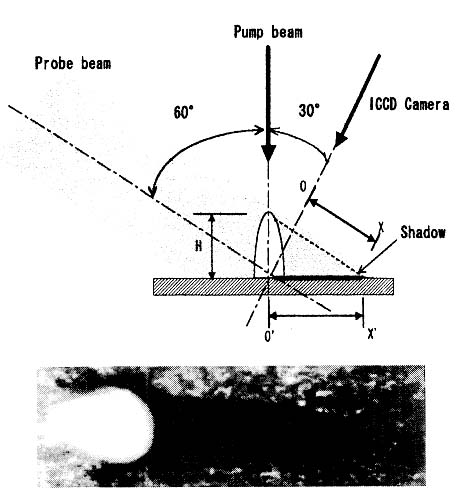
Figure 11 Experimental set up for plasma observation [Yoshiro ITO, et al., 1999]
Figure 11 shows the experimental set up. The image system is a kind of pump and probe technique in which time resolution is manily determined by the pulse of the illuminating light. Light pulse from Q-switched Nd:YAG laser with second harmonic generator contains both converted second harmonic radiation and remaining fundamental light. Both of them are delivered though proper light separation apparatus. After passing the apparatus, separated second harmonic light (532 nm) was used as illuminating light and the remaining fundamental light (1064nm) was used as ablating beam. The 1064nm light was focused onto the sample and hit the sample perpendicularly. When the distance from the lens to the sample was changed, laser spot size was changed and laser fluence can be changed while laser pulse energy is kept constant. The 532nm light passed illuminate the machining position at an angle of 60 degrees from the surface normal. Observation direction was at the opposite half plane with an angle 30 degrees from the normal. Images were captured by CCD camera equipped gated image intensifier. A band pass filter of 532 nm was placed in front of the camera. The gate width of the camera was 3ns and its timing was monitored by digital oscilloscope. The Nd:YAG laser delivered 6ns pulses measured as FWHM by a fast photodiode.
The system was used for a delay times of -5 to 25 ns. For longer delays, a second laser was used as illuminating source and the delay time between the two laser pulses was controlled by a digital delay generator (DG 535, Stanform Inst. CO.). In following pictures, white image is jet-like plasma growing from the surface and its shadow is clearer than bright plasma image itself, which allows us to calculate the its height precisely from geometry calculation shown in the figure. Shadow length is elnongated than actual plasma height. The image of a ruler put at the sample position was recorded prior to measurement and used as scale on a display to get actual dimensions. Actual plasma height is calculated by:
H= OX / cos(300),
where OX is the observed shadow length.
Figure 12 shows typical images of laser irradiated aluminum surface arranged with delay time. Laser fluence was 32 J/cm2 and irradiated in air. Bright plasma spot appear at 2ns and grows in height with time until 15ns. After 5ns, clear black shadow of this plasma is observed.After 30ns, both brightness of the plasma and the thickness of its shadow become dim. Growth speed of the plasma decreases and the plsama begin to expand to radial direction. In photograph at 100ns, bright image and its clear shadow dissapear and irradiated part on the surface becomes visible. These pictures are evidence of jet-like plasma.
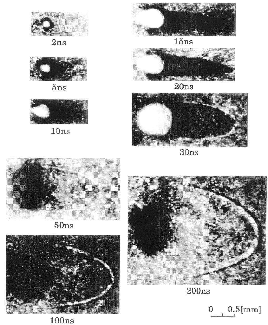
Figure 12: Typical images of plasma of laser irradiated aluminum surface[Yoshiro ITO, et al., 1999]
Using the above technique, the ablation of metals in various gas environment were observed. The growth of plasma jet, the direction of growth, and the effects of gases and metals were investigated. It was proved that when the laser fluence if high, a jet-like plasma column grows toward the incoming laser beam direction. Its growth speed during the laser pulse duration is of 105m/s, which is significantly faster than shock wave propagation under same pressure. The speed slows down to about 104m/s when the pulse is terminated. The growth speed increases with the laser fluence and is affected by gas environment but not by metal properties. A possible mechanism of the jet-like plasma would be the laser-induced breakdown of the gas by electrons ejected from the sample surface at the very beginning of the laser pulse.
References:
Tonshoff, et al., 1999, "Process and Condition Monitoring Features Incorporated in Laser Heads," ICALEO'99, E109-118.
Srinivasan, R., et al., 1989, "Ultrafast imaging of ultraviolet laser ablation and etching of polyethylmethacrylate," Appl. Phys. Lett., 55 (26), pp. 2790-2791.
Furutani, H., et al., 1998, "Laser induced decomposition and ablation dynamics studied by nanosecond interferometry," J. Phys. Chem., B102(18), pp. 3395-3401.
Chrisey, D. B. and Hubler, G. K., Editors, 1994, Pulsed laser deposition of thin films, New York, John Wiley & Sons, Inc., 1994.
Yoshiro ITO, et al., 1999, "Jet-like Plasma Formation in Laser Ablation of Metals Observed by Nanosecond Imaging Technique in Gases," ICALEO'1999, E61-70.
![]()
![]()