![]()
![]()
![]()
Level 2
Section 5.3: Introduction to laser machining of superalloys
Metallurgical response:
Laser machining is currently being used in machining superalloy. The laser ablates metal from the balance land in precise target locations and amounts at surface speeds as high as 30000 in/min. Laser machining is a fusion process where the metal that is not vaporized or removed during the liquid state resolidifies and becomes a recast layer. The solidification process of this recast layer is similar to that of the fusion welding process except that the amount of liquid metal is much smaller, normally 10 to 100 microns tick. The cooling rates are very fast because of the heat sink provided by the much greater size of the parent metal compared to the amount of recast layer.
Ni-based superalloy are widely used in turbine engine components. Air cooling hole drilling in such components is the most common machining process with lasers.
In the case of the conventional laser drilling, a recast layer is usually formed from the resolidified molten metal at the side walls. Typical average thickness of this layer is about 50 micron. Because of its rapid solidification, there are mircocracks formed in this recast layer that often extends into the parent material. These microcracks tend to reduce part life, and therefore recast layers are undesirable. Furthermore, the hole side walls are not straight, and the hole geometrical profiles varies significantly from hole to hole, because it takes just a few laser pulses of 1-10 J per pulse to drill a hole, thus render the process susceptible to variations in pulse energy and materials interaction s. In the case of the high intensity MOPA laser drilling, the recast layer is greatly reduced (Cronin, 1992). This must be attributed to the two orders of magnitude higher intensity and the shorter wavelength at the shorter wavelength (SHG). At this high intensity, materials removal is achieved predominantly by vaporization, not melt expulsion, as in the case of conventional laser drilling. Energy coupling into the material is also believed higher at the shorter SHG wavelength. The side walls are also much straighter, and the hole to hole consistency higher, because this process relies on thousands of pulses with much smaller pulse energies (about 10 mJ).
lntermetallic materials are being considered for future high temperature applications for its lower weight advantage. However, they tend to be very brittle and thus difficult to machine, as evidenced by the bulk cracking. Therefore, the conventional long pulse, low intensity lasa is not suitable for drilling of NiAl. Using the short pulse, high intensity at the ~530 mn wavelength, can solve this problem. The cut surface is nearly free of any recast layer or heat affected zones when the extremely high intensity ultrafast laser is used. Since typical thermal diffusion time is several picoseconds, the 100 fs pulse energy is deposited before any significant thermal diffusion, within the skin depth of the material. This forms a solid state plasma that eventually explodes and evaporates, leaving almost no melt or heat-affected zone. Because the pulse energy is so small (about 1mJ), any shock that is generated is weak, resulting in no microcraking even in the brittle ceramic alumina. Hence the femtosecond pulses can result in even better quality than the nanosecond pulses.
Applications
Let's take a look at a typical application of supperalloy laser machining in GE aircraft engines. By the mid-eighties, GE Corporate Research and Development (CRD) has successfully designed high brightness slab geometry lasers for military applications. A subsequent chain of events led to GE Aircraft Engines (GEAE) support of CRD development of an industrial quality slab or face pumped laser (FPL) system. The goal was a 500 Watt Nd:YAG laser system with brightness exceeding conventional rod laser systems. The system was to operate at commercial rod drilling laser parameters, eg. millisecond pulse durations, tens of joules per pulse, repetition rates up to 40 Hertz and beyond. The result was a laboratory prototype at CRD in 1986. The system had been designed to be installed in a commercially available rod laser PFN-based power supply and controller. GEAE worked with CRD to mount the laser in a commercial laser enclosure and the system was transitioned to GEAE in late 1986 to fully test the industrial FPL (IFPL) capability and begin application of the system to hardware. The prototype IFPL was integrated to a free-standing machine tool and CNC with an operating volume of 2.0 feet cubed. The initial capability studies showed by years end that the IFPL was a major advance in Nd:YAG laser technology by penetrating over two inches of nickel-based superalloy in less than two minutes of percussion drilling, and cutting 0.5 inch thick superalloy at up to 7.0 inches per minute. With the limited data on processing potential, production hardware applications were already obvious. As further capability studies and applications were developed, it was found that conventional rod laser process development could not always be applied in the case of the IFPL.
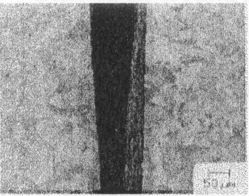
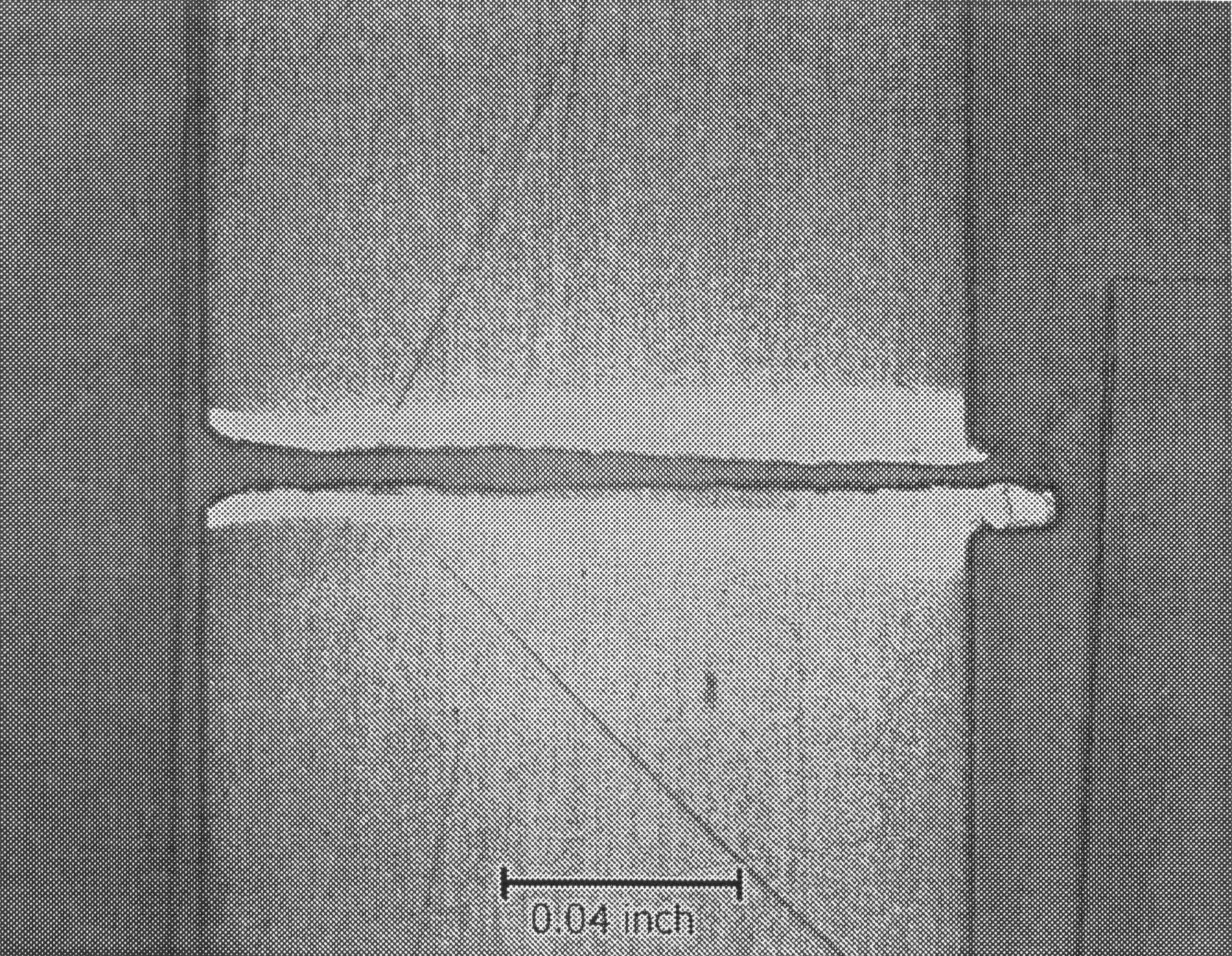
Improved hole drilling using a high peak power Nd:YAG laser at the second harmonic wavelength. Chen, X.L., et.al.,(1997) have previously described the drilling of advanced materials such as intermetallics, superalloys, and composites using an Nd:YAG laser operating at the fundamental wavelength of 1.064 µm. They show that drilling using the shorter wavelength further reduces undesired thermal effects such as recast layers and heat affected zones, and improves hole drilling using a high peak power Nd:YAG laser at the second harmonic wavelength. Shortening of pulse length and the subsequent increase in beam intensity result in much thinner recast layers and heat affected zones (HAZ), less microcracking or delamination of materials, and much better geometry stability. Ni-based superalloys are widely used in turbine engine components. Air cooling hole drilling in such components is the most common machining process with lasers. Figure 1 shows cross sections of holes drilled by (a) the conventional laser with 0.6 ms pulse width, 8.5x10⁶ W/cm2 intensity, and 1064 nm wavelength; and (b) SHG of Q-switched MOPA laser at 300 ns pulse width, 7x10E8 W/cm2 intensity, and 532 nm wavelength. The holes are drilled at a 30 degree angle from the surface.
Figure 1. Cross sections of holes drilled in N5 superalloy by: the conventional laser with 0.6 ms pulse width, 8.5x10⁶ W/cm2 intensity, and 1064 nm wavelength (left) ; and SHG of Q-switched MOPA laser at 300 ns pulse width, 7x10⁸ W/cm2 intensity, and 532 nm wavelength (right). (X. Chen, 1999)
In the case of the conventional laser drilling, a recast layer is usually formed from the resolidified molten metal at the side walls. Typical average thickness of this layer is about 50 micron. Because of its rapid solidification, there are mircocracks formed in this recast layer that often extends into the parent material. These microcracks tend to reduce part life, and therefore recast layers are undesirable. Furthermore, the hole side walls are not straight, and the hole geometrical profiles varies significantly from hole to hole, because it takes just a few laser pulses of 1 - 10 J per pulse to drill a hole, thus render the process susceptible to variations in pulse energy and materials interactions.
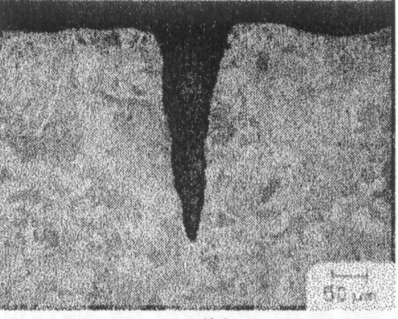
Figure 2. Laser cut quality comparison in Inconel 718. Left: Q-switched, frequency-doubled Nd:YAG laser (rod ossilator with slab amplifier), peak intensity 3*10E8W/cm2, pulse width 300ns, wavelenth 532nm. Right: Ti:sappire CPA laser peak intensity 1*10E15W/cm2, pulse width 100fs, wavelenth 790nm.
Figure 2. shows the quality comparison for cuts made in Inconel 718 between a Q-switched Nd.YAD laser at 300nspulsed width and a Ti:sappire Chirped Pulse Amplification (CPA) laser with 100fs, What is remarkable for the femtosecond laser is that no apparent recast, heat affected zone, or microcracking are observed. Since typical thermal diffusion time is severla picoseconds, the 100fs puls energy is deposited before any significant thermal diffusion, within the skin depth of the material. This forms a solid state plasma that eventually explodes and evaporates, leaving almost no melt or heat affected zone. Becuase the energy pulse is so small (about 1mJ), any shock that is generated is weak, resulting in no microcracking. Hence the femtosecond pulses can result in even better quality than the nanosecond pulses.
High powder CO2 and Nd-YAG laser has been widely used in welding machining of superalloy. High power laser welding techniques and related metallurgy have been investigated on Inconel 718 sheets (Gobbi, S., et. al., 1996) in annealed and aged states. The CO2 CW laser welded joint, with high depth to width ratio, is suitable for post welding machining. The uniform bead profiles were achieved by using an Nd-YAG pulsed laser, which have an overlapping rate of about 85%. Wrought Inconel 718 can be welded by laser in both annealed and aged states, but the grain size must be ASTM 10 or finer in order to control the microffissuring. The microfissures relate to the delta phase at fine grain boundaries (ASTM 9-12) and the NbC phase at large grain boundaries in particular, which occur in the delta phase band. The eutectic of the Gamma/NbC was suppressed by rapid solidification in the fusion zone. Many delta phases precipitate at interdendrites with 960°C post welding solution treatment. Above 1038 °C the laves phase dissolves completely and only NdC is present.
Recent advances in laser technology has enabled the achievement if high power and high quality beams by diode pumping of Nd:YAG slabs. TRW (Redono Beach, CA, USA) has produced a 3kW diode pumped Nd:YAG slab laser under the precision laser machining program funded by DARPA. The effectiveness of this laser was examined by Keng H. Leong, et. al., (1999) in a welding test on C95800nickel aluminum bronze. The beam parameters were 1700W at the workpiece, with a pulse repitition rate of 1000Hz and a pulse width of 170us.
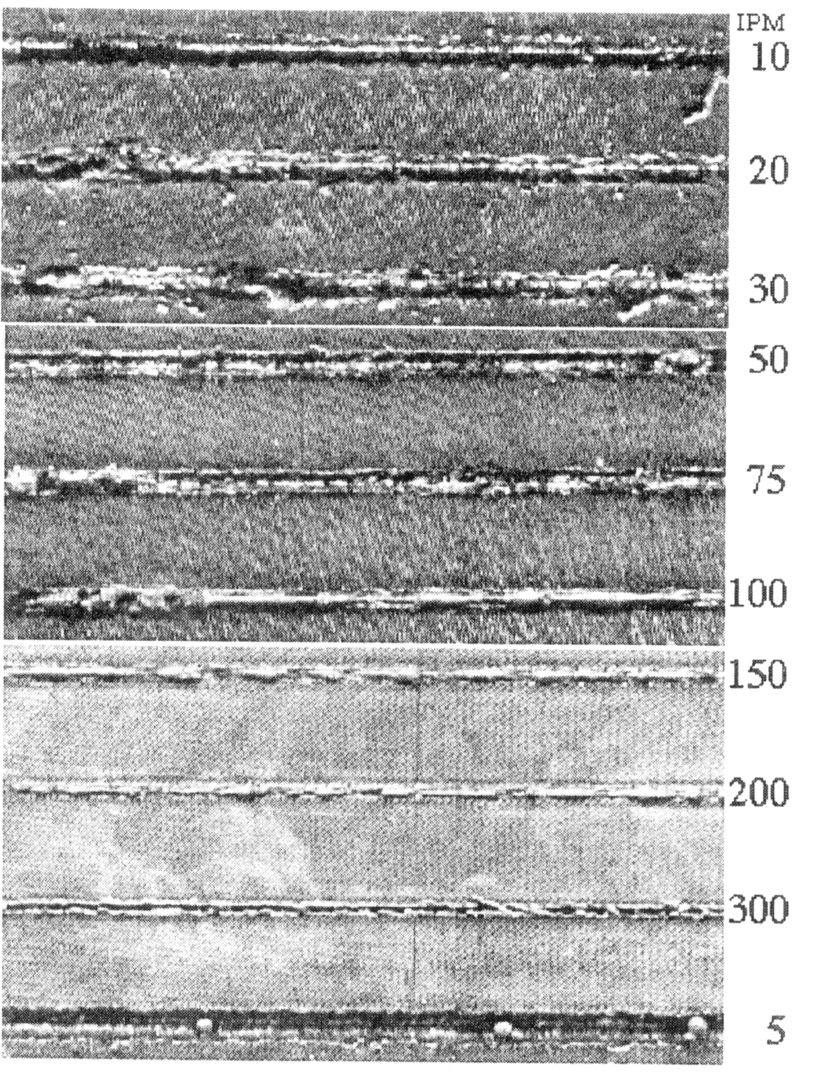
Figure 3. Photograph of the C95800nickel aluminum bronze samples processed at different speeds. The numbers o the right indicate the welding speed in ipm used. The distance between adjacent welds is 0.25 in.
The welds were obtained for welding speeds from 2.11 to 127 mm/s (5 to 300ipm) using the 517 mm focal lenth at 1700W to the workpiece. The surfece qualities of the welds produced are shown in Figure 3. At lowest speed (5 ipm), there is substantial undercut of 1.43 nm depth eith a weld penetration of 17mm. The undercut decreases monotonically to 0.4 mm at welding speed of 75 ipm as welding speed is increased. At 100 ipm, the undercut changed to humping as evident in Figure 3. However, at the maximum welding speed of 300 ipm, a cut of 1.1mm depth instead of a weld was produced. This trend of undercut is probably characteristic when using a high irradiance beam. The complex ineraction between the beam and the keyhole led to a surface humping profile and is not easily predicted.
Figure 5. Section of 4.8 mm Ti(6Al4V) cut by PLM high average power laser at 125W, 2500Hz eith 82.5 mm focal lenth lens, cut at 101 mm/s
Quality high speed laser cutting of Ti up to 31.8 mm thick has been demostrated by Warren Mather, te. al., (1999). They reported some significant advancements in laser cutting of metal. Figure 5. was done by using a repititively pulsed diode-pumped Nd:YAG laser whose power at the laser is 3kW. This is a high average power laser developed by TRW(Redono Beach, CA, USA) under the precision laser machining program. They concluded that : (1) very thick Ti can be cut by this kind of laser at 1750 W delivered average power, and (2) the narrow kerf delivered at very high speeds by this PLM laser cutting thin sheets allows much less waste heat to contribute to the heat affected zone.
![]()
![]()
![]()