![]()
![]()
![]()
Level 1
Section 5.1: Introduction to laser machining of Metals
Metals form solids in which the atoms are located in regularly defined, repeating positions throughout the structure. These regular repeating structures, known as crystals, give rise to specific properties. Metals are excellent conductors of electricity, are relatively strong, are dense, can be deformed into complex shapes, and are resistant to breaking in a brittle manner when subjected to high-impact forces. This set of mechanical and physical properties makes metals one of the most important classes of materials for both electrical and structural applications. Extensive (and in some cases exclusive) use of metals occurs in automobiles, airplanes, buildings, bridges, machine tools, ships, and many other applications where a combination of high strength and resistance to brittle fracture is required. In fact, it is largely the excellent combination of strength and toughness (i.e., resistance to fracture) that makes metals so attractive as structural materials. The basic understanding of metals and their properties is advanced, and they are considered to be mature materials with relatively little potential for major break- throughs. However, significant improvements have been and continue to be made as a result of advances in processing. Two examples are: Higher operating temperatures in jet engines have been attained through the use of turbine blades that are produced by controlled solidification processes. The blades are made of nickel and other metal alloys (atomic-scale mixtures of atoms) and are in wide commercial use. Improvements will continue as processes are refined through use of advanced sensors and real-time computer control.
The two classes of atomic bonds are primary and secondary bonds. Primary bonds are generally one or more orders of magnitude stronger than secondary bonds. The three malor types of primary bonds are ionic, covalent, and metallic bonds. All primary bonds involve either the transfer of electrons from one atom to another or the sharing of electrons between atoms.
Solids composed primarily of electropositive elements containing three or fewer valence electrons are generally held together metallic bonds. The electropositive elements can obtain a stable electron configuration by "giving up" their valence electrons. Since there are no electronegative atoms present to receive the "extra" electrons, they are instead donated to the structure in general. That is, they are shared by all of the atom in the compound.
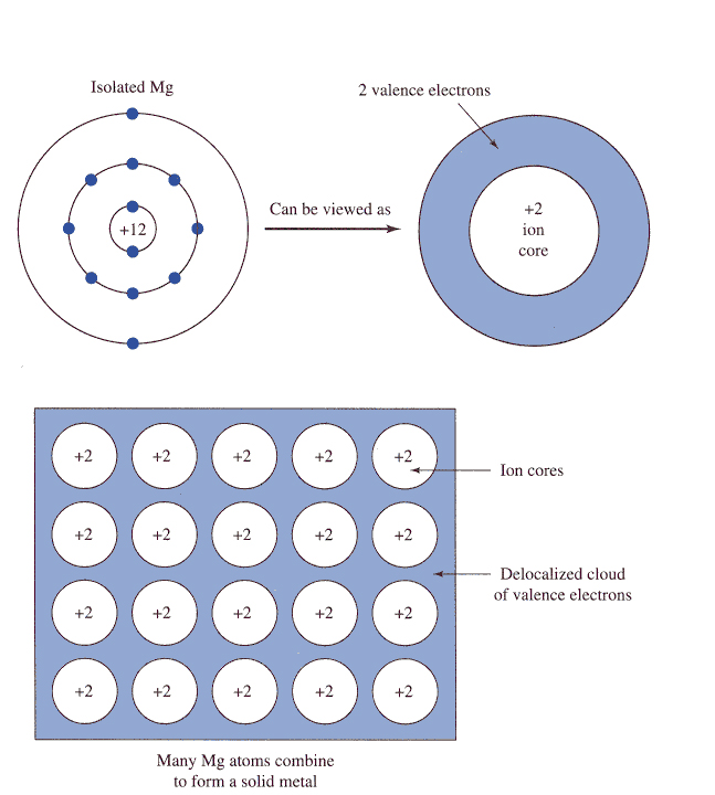
Figure (1) is a schematic representation of this bond in which the valence electrons are delocalized from the nucleus and core electrons. The valence electrons form a "cloud" or "sea" of electrons that surrounds the ion cores. The force holding the metal together is the attraction between the positively charged ion cores and the negatively charged electron cloud. The electrons are shared, but they are not spatially localized. As with the previous bond types, the Pauli exclusion principle results in a repulsive force that becomes significant when the filled electron shells associated with the ion cores begin to overlap. The sum of the attractive and repulsive forces leads to both bond-force and bond-energy curves similar in shape to those described for ionic and covalent bonds.
Fig. 1 A schematic representation of the metallic bond in solid Mg. The valence electrons form an electron cloud that surrounds the icon cores
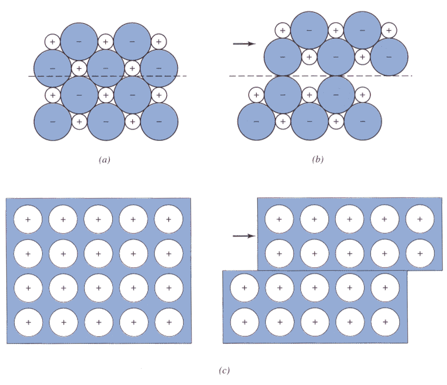
At this point we can make a few prelimilary observation concerning some of the mechanical and electrical properties of metals as a function of its bonding type. As show in the Fig. 2(c), atoms in the metal can slip and slide past another without regard to electrical-charge constraints in response to the applied force and thus absorb impact forces without break. On the other hand, as illustrated in Fig. 2(a)&(b), in an ionic solid, each icon is surrounded by oppositely charged ions. Thus, ionic slip may lead to like charge moving in ajacent positions, causing Columbic repulsion. This makes slipping much more difficult to acheive and the materials response by breaking.
Fig. 2 A comparison of the difference in atomic scale responde of a metal and an ionic solid to a impact.(a) In an ionic solid before the impact each ion is surrounded by oppositely charged ions; (b) When the ions attempt to slip past one another in response to the applied force, strong repulsive forces develop and lead to cracking; (c) In contrast, in a metal the electron cloud shields the positively charged atomic cores from each other so that the repulsive forces do not develop.
Next we consider the response of a solid to an applied electric field. Electrical conduction involves the directed motion of charges in response to an applied field. The electrical conductivity of materials depends on three factors: (1) the type of charge carrier in the materials (electrons or ions), (2) the spatial density of charge carriers, and (3) or ease with which the charge carriers can move through the atomic scale structure of the material.. The charge carriers in metals are the electrons in the cloud that surrounds the atomic cores. In part because of their small size, the loosely bound or free electrons can move relatively unimpeded through the metal, resulting in a high charge-carrier mobility. The combination of high mobility and high concentration of charge carriers leads to high electrical conductivities for most metals.
Drilling: Lasers are widely used in metal drilling applications due to the high processing speeds, high tolerance, repeatability and minute dimensions achievable In most industrial applications, both the penetration speed of the laser beam and the positioning speed from hole to hole are important; therefore, the values for drilling rate are given as holes per second and represent the total cycle time per hole. Usually, the holes created have eccentricity values below 5% and surface roughness below 5micron. Control of the drilling process for a given workpiece material is accomplished through selection of beam power, focal spot size, and drilling time. Laser drilling can be performed through continuous drilling, with the use of a continuous-wave beam, or percussion drilling, with the use of a pulsed beam. In continuous drilling, material removal occurs through melting with some vaporization. The molten material is ejected out of the bottom of the hole with the aid of a gas jet. In percussion drilling, a pulsed beam removes material through melting and localized detonation or explosion. In this case, about 90% of the material is removed through detonation effects. Additionally, a reactive gas jet can be used to remove material through oxidation, chemical reactions.
The effects of changing process variables such as gas jet pressure and lens/workpiece distance in laser drilling are studied by Yilbas (1988) using a pulsed Nd:Glass laser for stainless steel, titanium and nickel. Changes in gas pressure are brought about by the use of a vacuum on the hole exit side. Changes in lens/workpiece distance affect plasma formation inside the hole, which in turn affects the geometry and size of the melting front. Plasma formation is also affected by changes in pressure for the assist gas, which regulates the amount of high-temperature oxidation occurring in the hole. As the workpiece thickness decreases, the lens/workpiece distance required to achieve the best surface condition or the least amount of dross also decreases. For workpiece thicknesses less than 0.3mm, the lens/workpiece distance is greater than the lens focal length. These observations are verified by an experimental study of the effects of changing parameters on surface debris, dross formation, and hole taper.
For laser percussion-drilling processes on metals, drilling efficiency is strongly dependent on the phenomenon of laser-supported detonation waves. Plasma formation at the workpiece surface due to laser/material interaction severely decreases laser drilling effectiveness because it absorbs a significant portion of the incoming beam energy and thus shielding the workpiece surface. A laser-supported detonation (LSD) wave occurs when the absorbing plasma layer is coupled to a shock wave occurring when material at the erosion front detonates. This transient phenomenon propagates the plasma volume and effectively shields the workpiece surface from the laser beam. LSD wave effects can be minimized by using a shorter focal length lens, by increasing the beam intensity and by using a low density gas jet such as He instead of air.
Cutting: The laser cutting industry is dominated by the profiling of steel sheet of both mild and stainless grades. The cuttingprocess is achieved by a combination of laser heating and the chemical reaction of iron with oxygen. This oxidation reaction is exothermic (heat generating) and acts as a secondary energy source which helps to accelerate the cutting process. Basically, the metal is locally heated by the focused laser beam to a temperature at which the iron will ignite in the oxygen jet acting coaxially with the beam. During laser cutting materials are subjected to physical and/or chemical damage over a narrow area throughout the depth of the sheet.
Mild steel is the most important of the materials which undergo a laser activated chemical reaction during cutting. This chemical reaction (the oxidisation of iron) increases the cutting speed and quality compared with simple laser melt cutting, but has the unfortunate side effect of increasing the sensitivity of the process to certain parameters, particularly:
1. Nozzle-beam misalignment or nozzle contamination
2. Poor axial symmetry of the laser mode
3. Contamination of the oxygen supply
4. Local overheating of the workpiece as a result of poor CNC programming
Apart from these four parameters, the cutting process has a remarkably large "operating window" within which excellent cutting results can be achieved, unless maximum possible cutting speeds are required. Most experienced laser users establish the maximum cutting speed for a particular steel sheet thickness and then work at between 80 and 90% of that value. This practice ensures that the cutting machine is working well inside its limits and is therefore rendered relatively insensitive to minor changes in other process parameters (laser power, focus position, sheet condition, oxygen supply, etc)
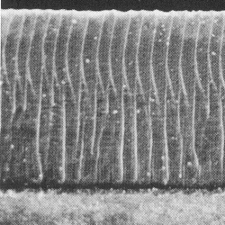
The Cutting Mechanism for Mild Steels Observation of any mild steel cut edge produced by a combination of a CO2 laser and an oxygen jet will reveal regular spaced ripples or "striations" along the cut edge as shown in Figure (3). In thin section steel (<4mm) these striations may be clear and regular from the top of the cut edge to the bottom. However, on thicker sections, the striations may be clear towards the top of the edge but are replaced towards the bottom by more random ripples associated with the flow of liquid out of the cut zone. The striations are evidence that even though the energy input to the cutting zone (i.e. laser energy and oxygen flow) is constant, the interaction between the metal and the incident energy behaves in a cyclic manner. One of the earliest and clearest explanations of this cyclic reaction was developed by a team from Osaka University led by Arata and Miyamoto (1981). This simple model can be described as follows:
1. The Laser and its co-axial oxygen jet move onto the edge of the steel sheet and the steel is locally heated by the focused laser to a tempera- ture at which it will ignite in the oxygen.stream.
2. The burning front thus established is fed energy directly from the Lasers and also from the exothermic oxidation reaction. This highly energetic environment causes the burn front to move rapidly away from the centre of the laser beam.
3. Once the laser beam has been left behind, the burning front cools and extinguishes.
4. The moving laser then initiates the re-ignition of the next area to repeat the process and thus generate a pattern of striations along the cut edge. The cyclic nature of the laser-oxygen-steel reaction which generates the striations is the major clue to a full understanding of the process and many conflicting models have been put forward to explain this phenomenon. The model outlined above provides a basic introduction to the cutting mechnism without resorting to complex mathematics. The interactions in the cut zone are, of course, more complicated than outlined here and involve fluid and gas dynamics as themodynamics.
Fig. 3 A typical mild steel cut edge showing he distinctive striation pattern (the sample shown is 2.0mm thick.) (John Powell, 1993)
Scribing and Marking: Laser scribing and marking on metals has been shown to be economically viable for some engineering applications as well as for part identification in industry. Laser marking systems are currently employed in the electmnics, cosmetics, food and beverage, and optical industries, among others. Engineering applications include the grooving of micro-channels for cooling systems and the creation of slots for assembly. The engraving of products with alphanumeric or bar codes, logos, symbols and graphics are also useful applications for CO2 and ND:YAG lasers. Laser marking compares favorably with other marking systems, when the comparison is based on throughput, performance and flexibility.
The basic requirements for a CO2 laser marking system include a Transversely Excited Laser (TEA), power supply, modulator, gas jet, motor control electronics, two beams including folding mirrors and imaging lenses, and a detection system to guide the beam scanning direction. The laser generates a high peak energy which vaparizes the surface of most metals and creates deep, clean scribe lines to form patterns on a niewlic surface. One typical industrial CO2 laser marking application can be found in the pharmaceutical industry, where lasers are used to mark statutory information such as manufacture and expiration dates on the crimped end of collapsible creams tubes. The use of laser marking negates the difficulty associated with preprinting. Laser marking is also used in the distillery industry, where lasers apply permanent security codes to the side of the bottle.
ND:YAG laser marking systems usually operate in one of two modes: dot matrix and continuous lines. Each functions differently and each is suited for specific applications.The dot matrix systems utilize a pulsed ND:YAG laser in conjunction with a raster scanning beam delivery system. Dot matrix marking is effective for relatively large length scales (greater than Imm), but is not suitable for small lettering applications, where the distance between dots approaches the maximum excursion of the line. Continuous line marking systems, which produce legible alphanumeric characters, are the most commonly used laser markers. With continuous marking, small lettering or fancy scripts can be created. The achievable groove depths depend primarily on the workpiece material and the energy density as applied to the workpiece. Some representative applications for YAG laser engraving include marking nameplates, bar code marking and medical applications. Future expansion of laser engraving will significantly depend on developments in computer motion control, imaging systems and robotics.
For details of Basic Constructions of Lasers, please refer Level 1 chapter 2 section 2.4
![]()
![]()
![]()