![]()
![]()
![]()
Level 3
Section 5.1: Diode Laser Machining Overview
Introduction
As tools for use in industrial applications, high-powered direct diode lasers, also known as semiconductor lasers, are becoming more prevalent. Diode laser technology has been used for a number of years in compact disks and laser printers and laser pointers. Their low cost, high efficiency, and compact design make them an attractive technology in the manufacturing environment.
Laser Diodes, sometimes called injection lasers, are similar to light-emitting diodes [LEDs]. In forward bias [p-side +], electrons are injected across the P-N junction into the semiconductor to create light. These photons are emitted in all directions from the plane on the P-N junction. To achieve lasing, mirrors for feedback and a waveguide to confine the light distribution are provided. The mirrors of a laser diode are cleaved facets of the III-V (AlGaAs) semiconductor from which the laser are made. 1 AlGaAs lasers can be made to emit between 0.72 and 0.88 gm. InGaAs emit photons having a characteristic wavelength of between 0.88 and 0.98 gm. High power diode lasers are composed of many individual laser cavities that are processed into a single bar. The light emitted from an array of laser diode bars is asymmetric. Each bar is capable of emitting 65 watts and having a conversion efficiency of greater than 50%. The remaining heat due to joule heating is removed by mounting the laser diodes on microchannel water-cooled heatsinks.
The light emitted at the facet of the laser diode is highly divergent and to make this usable, micro-optics are precisely mounted parallel in front of each laser diode bar. Since the other axis referred to as the "slow axis," is not collimated and is left to diverge the final focusing lens will produce a concentrated line of light. This produces a beam having a nearly rectangular intensity profile along the line with a guassian profile perpendicular to the line. For example, the 3.0kW laser used four stacks of 20 bars, which are brought to a line by a single macro lens. This can be used to generate power densities as high as 100 kW/cm2. This type of arrangement provides an ideal heat source for applications involving large surface areas. Since the power densities are lower than that typically required creating a "key hole," processing is performed during this investigation in the 'conduction' mode.
System efficiency is another advantage of direct diode lasers. When comparing the amount of output laser energy for a given electrical input, the efficiency of the direct diode laser is much higher than that of conventional laser systems. Another advantage of direct diode lasers is that they are solid-state lasers. This yields a highly controllable heat source. The advantages of direct diode lasers are then decreased footprint, lower maintenance, and less power to operate than lasers typically used in industrial environments. Finally, direct diode lasers are relatively small and compact, such that the laser head can easily be mounted to a robotic arm or gantry for use.
Laser sysetm:
Fig. 1 shows a 50w class direct diode laser combination system, which was developed by Nobuyuki ABE, et. al.,(1998) to examine the effectiveness of combining the beams from 4 diode arrays into 1 beam using both polarization coupling and wavelength coupling as shown. Three mirrors, two polarizing beam splitter cubes, two quartz polarization rotators and a dichronic mirror were prepared for optical combination of the four 15W diode arrays with a beam shaper. The wavelengths of the two pairs of 15W diode arrays were 810nm and 950nm, respectively. A quartz polarization rotator was set up on the exit aperture of one of the diode arrays in each pair. For each pair of diode arrays, the splitter cube reflects the beam polarized 90' by the rotator at a right angle, while at the same time letting the reflected beam from the other diode array pass through. In this way the beams produced by each pair of diode arrays are combined at the splitter cubes. The beams that exit the splitter cubes each have different wavelengths (810nm and 950nm) and approach the dichroic mirror from different directions. The 950nm beam passed through the dichronic mirror, while the 810nm beam is reflected at a right angle, with the result that they combine into a single beam. An achromatic lens then focuses the combined beam at a focal distance of 21.1mm.
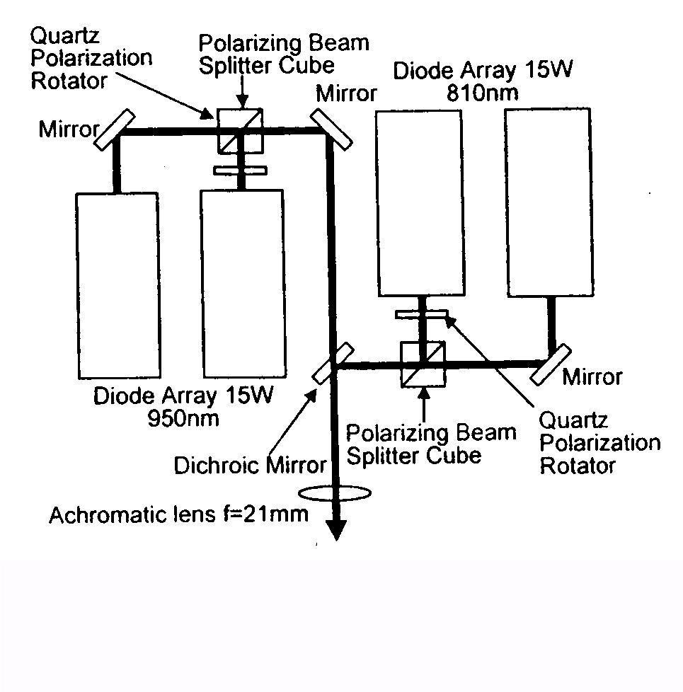
Fig. 1 a 50w class direct diode laser combination system. (Nobuyuki Abe, et. al., 1998)
Applications
There are varieties of potential applications for diode lasers. The great advantage of the direct diode laser is that all the applications described herein can be performed with the same laser system without the need for changing tools or optics. This could ultimately provide manufacturers with tremendous flexibility.
Welding
Plastic Welding: In this experiment, welds were conducted on two sheets of plastic at the faying surfaces. A translucent plastic was placed above an opaque plastic, both 3.175 mm thick, and welded. Trials were conducted at 700 W, focused beam, with 33 I/min of argon shielding gas. It was desired that the laser beams penetrate through the translucent top-piece and become absorbed in the opaque bottom-piece, thus forming the weld at the faying surfaces. The optimal results were achieved at a travel speed of 6.35 meters per minute. A travel speed of 7.62 m/min provided insufficient heat input to melt the plastic and 5 m/min produced a visible melt on the surface of the translucent piece, which was not desired.
Steel Welding: The welding of stainless steel 304 was also investigated with the direct diode laser using the six-axis robot. The goal of this investigation was to obtain complete penetration of the specimen, while providing little distortion, and good weld quality. The thickness of the stainless steel was 0.6 and 0.9 mm and each piece was approximately five centimeters by ten centimeters in size. The weld was made along the 10-centimeter side.
The welds that resulted at all powers were aesthetically smooth, showing very little oxidation on the surface. A micrograph of a stainless steel 304 weld is shown in Fig. 2.
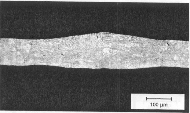
Fig. 2 cross section of a welding seam, stainless steel, high power diode laser 500W, 6000mm/min (236ipm) (after S.Bonss, et. al., 1998)
Surface Transformation Hardening
Laser surface transformation hardening is the heating of a surface by use of a laser and then allowing rapid quenching by conduction. This provides a hardening on the surface of the material through a solid-state transformation that results in the formation of a high-hardness microstructure, i.e. martensite. The depth of the hardened zone may be altered by varying the amount of heat input provided to the work-piece. In this evaluation, heat input was altered by varying travel speed. During these evaluations, the length dimension of the spot of focus, which was approximately 12 to 14 mm, was directed perpendicular to the direction of processing. This allows very large surface areas to be hardened in a single pass. Laser surface transformation hardening is often used to harden localized areas of machine components such as gears and bearing surfaces. A flat-topped gaussian-shaped hardened zone is obtained through a laser beam surface treatment.
Since the diode laser is modular in design, many stacks may be placed side by side to create an unlimited laser heat-treated width. Also, the phenomenon of superhardening occurs when multiple, overlapping passes are conducted with the diode laser. During superhardening, the formation of austenite from martensite is extremely rapid, thus, inducing imperfections that subsequently affect the strength of the martensite. However, in the interpass zone, backtempering can also occur because the heat generated in the second pass causes a portion of the initial pass to be raised to a temperature at which tempering occurs. Thus, the supersaturation of the quenched martensite is relieved and equilibrium mixtures of phases are approached. Tempering results in a decrease in the strength and hardness and a microstructure of tempered martensite. The back tempered region is generally 1 to 3 mm wide with a 40 to 50 Rockwell C hardness range.
Hardening of a the cutting edges can be made by induction or laser hardening. Induction hardening is a very effective method for hardening cylindrical geometry, but tools like side-cutting pliers have a completely different shape. By adjusting feed rate and laser power exactly to each position of the hardened zone the problem could be solved by laser hardening. The results is shown in cross sections in Fig. 3. The hardness of the bright zone is about 850 HV. Fig. 4 shows the diode laser hardened side-cutting pliers after 5 min cutting spring steel wire. The cutting edge is still very smooth.
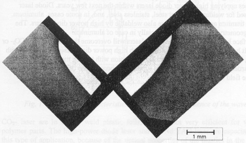
Fig.3 Cross section of diode laser hardened side-cutting pliers (after S.Bonss, et. al., 1998)
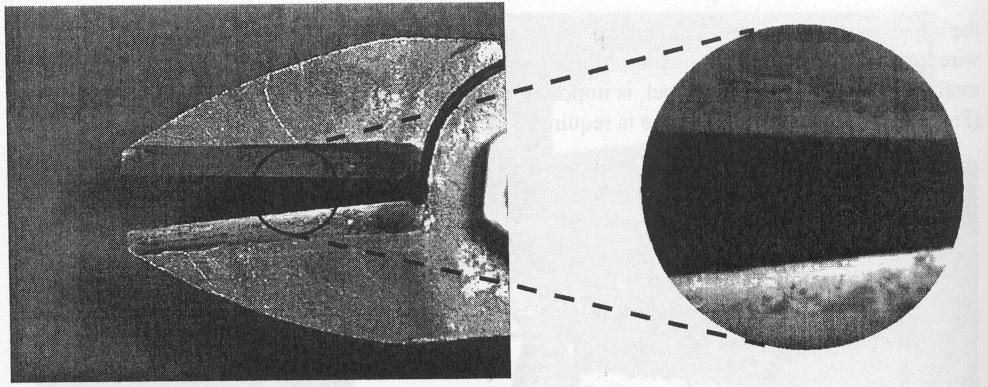
Fig.4 diode laser hardened side-cutting pliers after cutting spring steel wire (after S.Bonss, et. al., 1998)
Cladding
Laser cladding was investigated for its applicability with the direct diode laser (Steffen Nowotny, et. al., 1998). Loose powder of Inconel Tm 625, Stellite Tm 6, or stainless steel 420 was pre-placed onto a 4140 steel substrate and melted with the laser. Complete fusion of the clad material with the base material was desired. For each material, the loose powder was placed 1.20 mm thick and 14 mm wide. During each of the laser cladding evaluations, the length dimension of the spot at focus, which was approximately 12 to 14 mm, was directed perpendicular to the direction of processing. This resulted in a larger area of powder being melted. Also, for these investigations, the laser beam was at focus on the top surface of the work piece. The cladding materials were chosen based on their application in industry to provide hard, corrosion resistant, and wear-resistant surfaces. No cover gas was used during the laser cladding operation. Dilution into the substrate, which is the ratio of the intermixed zone and the clad thickness was determined to be less than 1%. laser cladding performed with the CO2 or Nd: YAG lasers generally yields a dilution of less than 5%. Note also that the deposit efficiency of laser cladding with the direct diode laser is in the range of 85 to 95%.
The Vickers hardness number of each material that was clad as evaluated from the top of the clad into the substrate. Investigation of reveals that the Stellite TM 6 and stainless steel 420 provided a significant increase in hardness, whereas, the lnconel tm 625 displayed very little increase in hardness. It should be noted that the Vickers hardness numbers of the Inconel TM 625, StelliteTm6, and stainless steel 420 obtained during this investigation are very similar to hardness obtained through laser cladding using higher power CO2 laser System.
References:
S.Bonss, et. al., 1998 "Diode LAser Applications Hardening and welding," ICALEO, 1998 G-121
Satish V.Ponnaluri, et. al., 1998 "Diode Laser Scribing of Amorphous Alloys for Core Loss Reduction in Distribution Transformers," ICALEO 1998, G-103
H.D.Hoffmann, et. al., 1998 "A new Diode pumped CW-multi-KW-solid State Laser Source system performance and first applications in Materials Processing," ICALEO 1998, G-1
Nubuyuki Abe, et. al., 1998 "Processing Characteristics of a high Energy Density Diode Laser System," ICALEO 1998, G-95
Nowotny, Steffen; Mueller, Anne; Techel, Anja; Franz, Ulrich, 1997 "Laser surface cladding of aluminum with oxide ceramics" Author Affiliation: Fraunhofer Inst fuer Werkstoffund Strahltechnik Source: Laser Institute of America, Proceedings v 83 n 2 Nov 17-20 1997 p F37-F44
![]()
![]()
![]()