![]()
![]()
![]()
Section 5.1: Introduction to laser machining of ceramics
Ceramics Ceramics are composed of both metallic and nonmetallic atomic species. Many (but not all) ceramics are crystalline, and frequently the nonmetal is oxygen, as in A12O3, MgO, and CaO, all of which are typical ceramics. One significant difference between ceramics and metals is that in ceramics, bonding is ionic and/or covalent. As a result there are no "free" electrons in ceramics. They are generally poor conductors of electricity, but are frequently used as insulators in electrical applications. One familiar example is spark plugs, in which a ceramic insulator separates the metal compo- nents. Ionic and covalent bonds are extremely strong. As a result, ceramic materials are intrinsically stronger than metals. However, because of their more complex structure, the ions/atoms cannot easily be displaced as a result of applied forces. Rather than bend to accommodate such forces, ceramics tend to fracture in a brittle manner. This brittleness generally limits their use as structural materials, although recent improvements have been made by incorporating ceramic fibers into a ceramic matrix and other innovative techniques. Their rigid bond structure confers other advantages, including high temperature stability, resistance to chemical attack, and resistance to absorption of foreign substances. They are thus ideal in high-temperature applications such as the space shuttle, as containers for reactive chemicals, and hs bowls and plates for foods where surface contamination is undesirable.
Some ceramics are not crystalline. The most common example is window glass, which is composed of various metal oxides. Optical properties are of major importance in glass and may be controlled through composition and processing. In addition the thermal and mechanical properties of glass can also be controlled. Safety glass is simply glass that has been subjected to a thermal cycle that leaves the surface in a state of compression and thereby resistant to cracking. In fact, glass treated in this way is even difficult to crack when struck with a hammer! Some current and potential applications for ceramic materials with a large economic impact are listed below: In the automotive industry the thermal and strength properties of ceramics make them very attractive for engine components. For example, there are over 60,000 autos in Japan with ceramic turbochargers, which increase the efficiency of the automobile. The materials in this application are Si3N4 or SiC processed to have some ability to resist brittle fracture. Ceramics based on compounds such as YBa2Cu3O7 and Ba2Sr2CaCU20, have increased critical superconducting temperatures to >95K. This means that superconducting films may be used as liners in microwave devices and as wires for all kinds of applications. Improving the current carrying capacity and connection technology are essential for widespread application of these materials. Next-generation computers will have ceramic electro-optic components that will give increased speed and efficiency.
Drilling:
Lasers can be used very successfully in machining of ceramic materials. Due to their high hardness and brittleness, conventional machining of ceramics by mechanical or ultrasonic methods is costly and time-consuming. For example, ultrasonic drilling of aluminum oxide requires approximately 30 seconds per hole; furthermore, the cost of ultrasonic drilling is approximately three times that for laser drilling. Mechanical drilling requires additional operations such as attaching the workpiece to a fixture with adhesives prior to drilling, and a cleaning operation after drilling. Laser drilling can be a more time- and cost-efficient process. Laser machining can be applied either before or after "firing" of the ceramic material. However, some drilling operations have also been performed on "green",(unfired ceramic workpieces), substrate materials. Two major problems exist with laser machining of green substrates. First, since laser machining produces localized heating, the material near the rim of the hole becomes brittle and may break off; Second, during the firing process, anisotropic shrinkage of up to 20% may occur, causing large deviations in dimensional accuracy of the machined part. Like metals, ceramic materials can be drilled by percussion (Figure 1) on materials such as aluminum oxide (Figure 2).
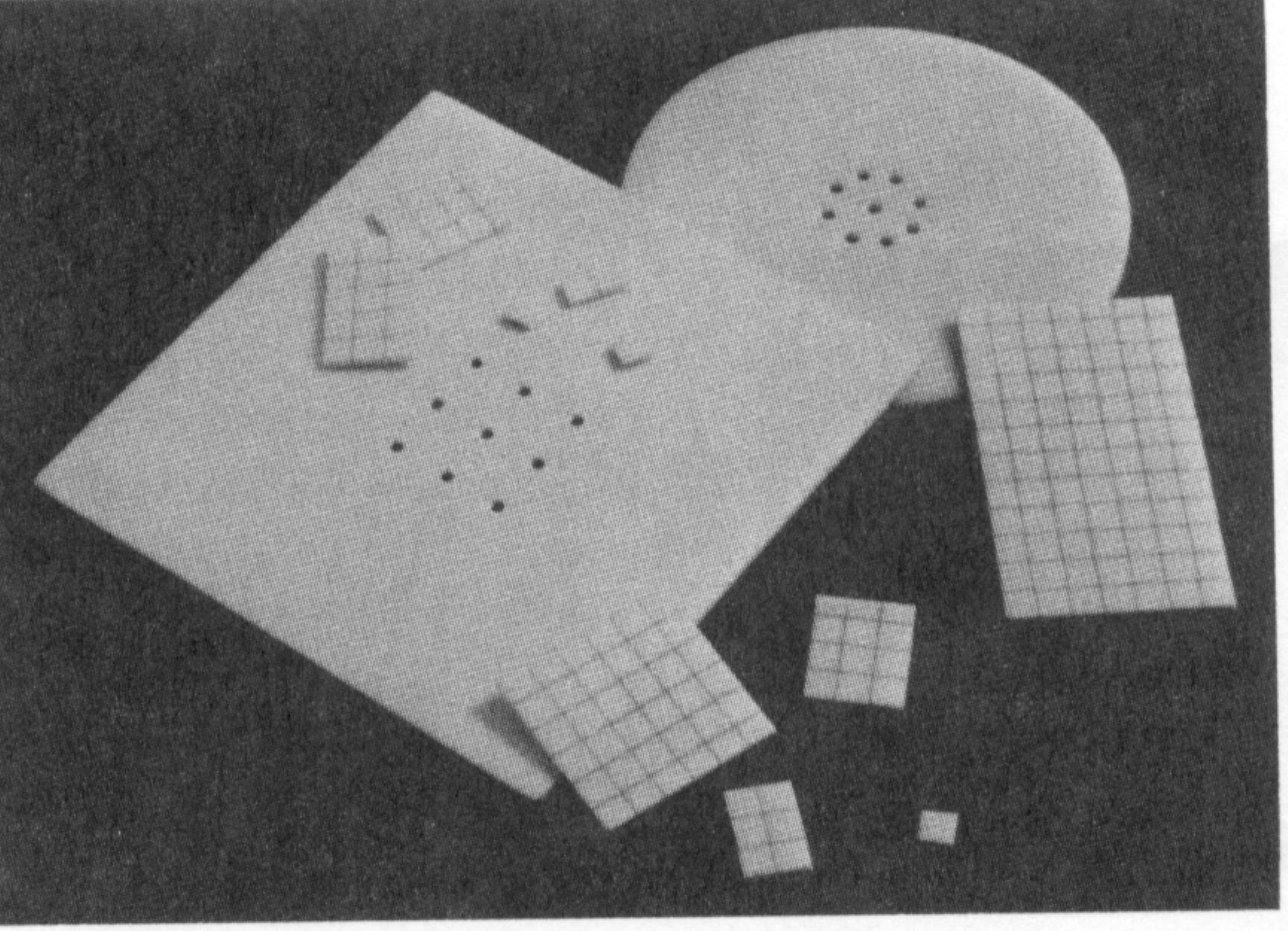
Fig. 1 Laser-drilled Alumnia Substrate (Laudel, 1980)
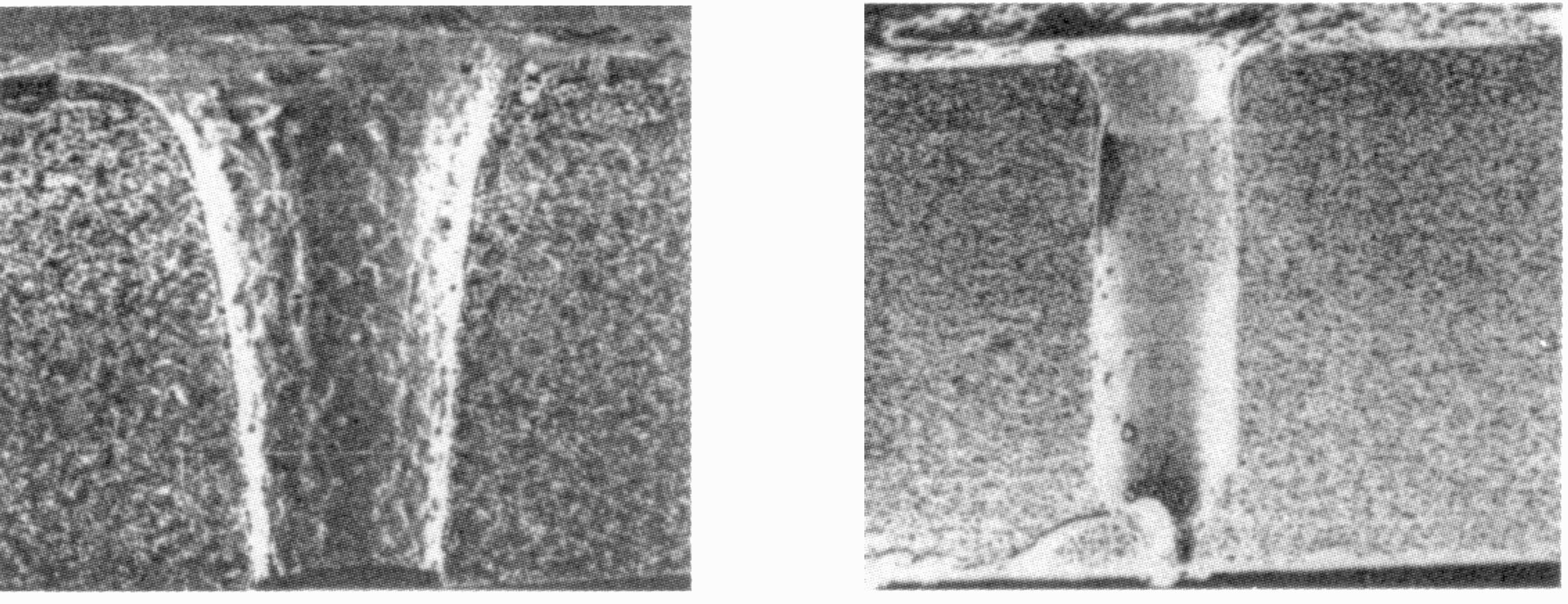
Fig. 2 Comparison of Pulsed CO2 and Pulsed ND:YAG Laser-Drilled Holes in Aluminum Oxide (Hamann and Rosen,1987)
One consideration in laser drilling of ceramics is the energy required to initiate drilling. A threshold energy density value is defined as the energy density level below which material removal is not possible. For uncoated aluminum oxide (Wagner,1974), the threshold energy density ranges from 750J/cm2. to 1000J/cm2. This energy density threshold can be decreased to approximately 400J/cm2 by coating the top surface of the workpiece with gold, which has a relatively high thermal conductivity.
One problem encountered in ceramic drilling is the resolidified material which forms in the hole. Since the melting temperatures for ceramic materials are high, material removal occurs primarily through melting and a molten layer is formed at the erosion front. Due to the limited space in the hole, expulsion of molten material with a gas jet is difficult. Tle remaining recast layer reduces hole depth by absorbing beam energy and degrades surface quality by increasing hole surface roughness. This problem was addressed by coating the substrate with polyvinyl alcohol prior to drilling. The coating aiinimized adhesion of recast material around the hole entrance. The recast layer inside the hole was removed by a secondary glass bead peening process. Micro-crack formation near the drilled hole is another problem encountered in laser drilling of ceramics (Figure 3). Cracks are induced by rapid heating during laser processing, which causes large temperature gradients near the hole surface. Microcracking can be minimized by preheating the workpiece to an elevated temperature prior to laser machining. In this manner, the temperature gradients achieved during laser machining will be reduced significantly compared to laser drilling of a cold workpiece.
Fig. 3 Crack formation in CO2(left) and Nd:Yag Laser-drilled holes(right). (Harrysson and Herbertsson,1987)
Cutting:
Conventional cutting of ceramic materials is usually done with a diamond saw. Although this gives a high surface quality, the cutting speed is low, typically around 20mm/min. Laser cutting allows cutting speeds up to 1200mm/min, a significant increase over conventional machining, without sacrificing surface quality . Material removal occured primarily through local vaporization of the material.
By Affolter and Schmid (1987), aluminum oxide material up to 15mm thick was cut with a l0kW ND:YAG laser and a cutting speed from 10mm/min to 20mm/min. The resulting kerf surface had a roughness of less than 2um RMS. Tne best results (small taper, smooth surface, minimal micro-cracking, and large cutting depth) could be achieved by using high pulse energies and a high pressure assist gas (a 600kpa N2 jet). By using the same laser conditions, silicon carbide workpieces up to 5mm thick could be cut with a speed of 40mn/min, 3mm thick silicon nitride material could be cut at 50mm/min, and 1.3mm thick zirconium oxide could be machined at 200mm/min. Material in the kerf was melted and either ejected by a gas jet or partially evaporated.
One method for minimizing micro-crack formation is to preheat the workpiece to a high temperature prior to interaction with the laser beam. This procedure minimizes the temperature gradients and thermal stresses in the workpiece during laser machining. Laser cutting of silicon nitride, silicon carbide, and magnesia-stabilized zirconia (PSZ) workpieces were also investigated (Firestone and Vesely, 1988) using a 15 kW CW CO2 laser with a minimum spot diameter of 2.7mm. To minimize cracking, the specimens were heated first in a furnace to 1400'C. A gas jet was used to reduce oxidation and prevent plasma formation. Silicon nitride requires a heating and cooling sequence to avoid fracture; the specimens were first heated to 1000'C in 200'C steps, then machined and allowed to cool to ambient temperature. Beam power ranged from 1to 4 kW with cutting speeds ranging from 15mm/min to 150mm/min. For the experiments in which one beam pass was made, the specimen did not fracture. The width of the groove ranged from, 0.66mm to 4rnm at the top and from 0mm to 2.3mm at the bottom. The depth ranged from 6.35um to 740um. PSZ was machined at 1225'F and 1825'F with single and multiple passes. The beam power ranged from 2kW to 6kW and the cutting speed varied from 9100 to 16000mn/min. The resulting depth of cut for PSZ ranged from 0.13mm to 0.9mm. In general, higher beam power and preheat temperature resulted in higher material removal rates.
Scribing and marking:
Laser scribing has been used for high-speed marking of identification labels on ceramic parts. Laser scribing has also been used in the electronics industry for producing snap lines in aluminum oxide wafers during fabrication of circuit boards. Snap lines from 0.08 to 0.2 mm deep were formed using 50W and 125W pulsed CO2 lasers with a focussed beam diameter of 140gm. The pulse frequency was 250Hz, pulse durations varied from 0.28 to 0.8 ms, and the scanning velocity was 80mm/s. Microscopic analysis of the workpiece surface showed the appearance of micro-cracks along the snap line. A thin layer of molten material was also found. Solidification of molten material led to material shrinkage, which resulted in residual stresses near the snap line.
By Affolter and Schmid (1987), a scribe line 40gm deep was produced busing a 80W pulsed CO2 laser and a scanning velocity of 5m/min. Micro-crack formation in the workpiece was minimized by reducing the pulse duration to 50ms. At this pulse duration, the boundary between the recast layer and the workpiece material served as an effective barrier to niicro-crack propagation. By Hamann and Rosen (1987), 63mm deep snap lines were produced using both CO2 lasers, with scribing speeds ranging from 15mm/s to 7mm/s, and ND:YAG lasers, with scribing speed of 7.5mm/s.
The energy efficiency was found to be close to maximum up to a groove depth equal to four times the spot diameter (Chryssolouris, et.al., 1988). For larger groove depths, the energy efficiency decreased For groove depths over 30 times the spot diameter, the energy efficiency was reduced considerably. For deep grooves, formation of resolidified material along the groove waus becomes a significant effect; the resolidified material reduces energy efficiency by absorbing beam energy which would otherwise remove additional material. The recast layer, which also degrades the surface quality (Figure 4), can be minimized by using an off- axial gas jet to expel molten material. A series of grooves can be produced in an alumina workpiece to form cooling channels (Figure 5).
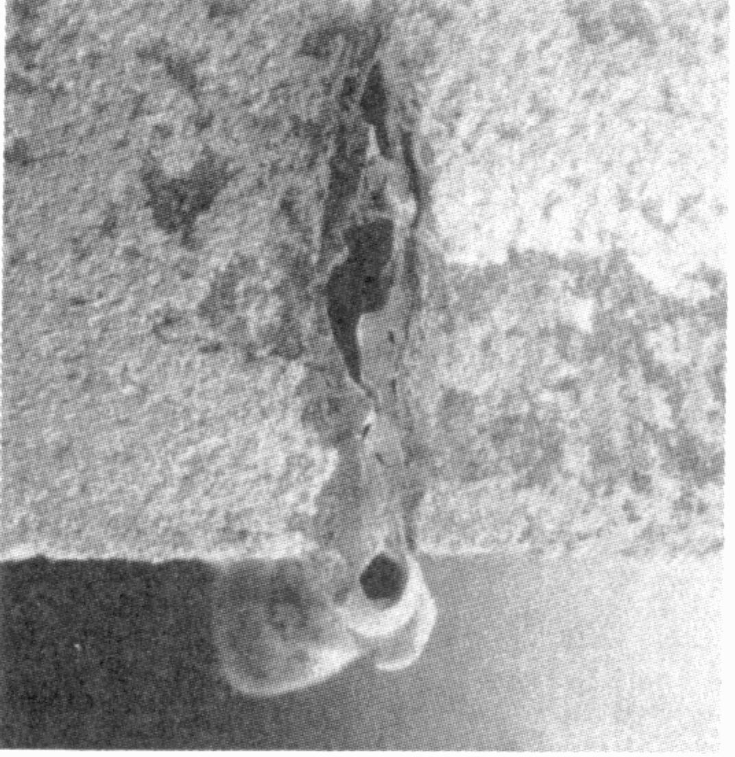
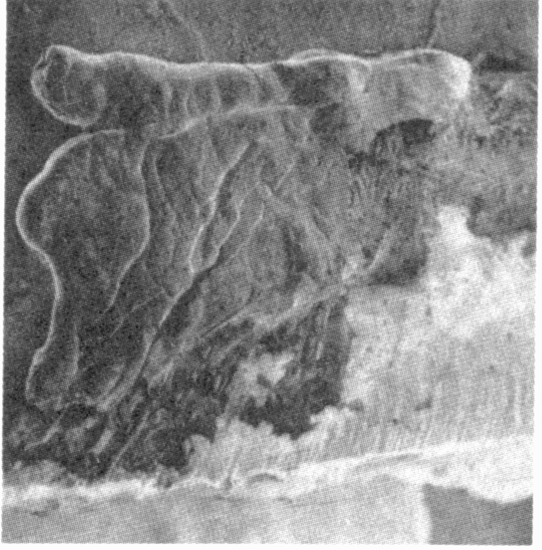
Fig. 4 SEM cross section (left, 30x) and side view (right, 190x) of laser-cut groove in Alumina (Chryssolouris, et.al., 1988)
Tungsten carbide material can be scribed using high laser power and low scanning velocity. By Affolter and Schmid (1987), a l0kw ND:YAG laser was used with a 30Hz pulse rate and a 0.1ms pulse duration. A 40um deep scribe line was machined with a scanning velocity of 54mm/min. When the scanning velocity was reduced to 27mm/min, the width of the scribe line increased, while the distance between perforations decreased. The thermal damage to the workpiece could be reduced by using two beam passes at 54mm/min.
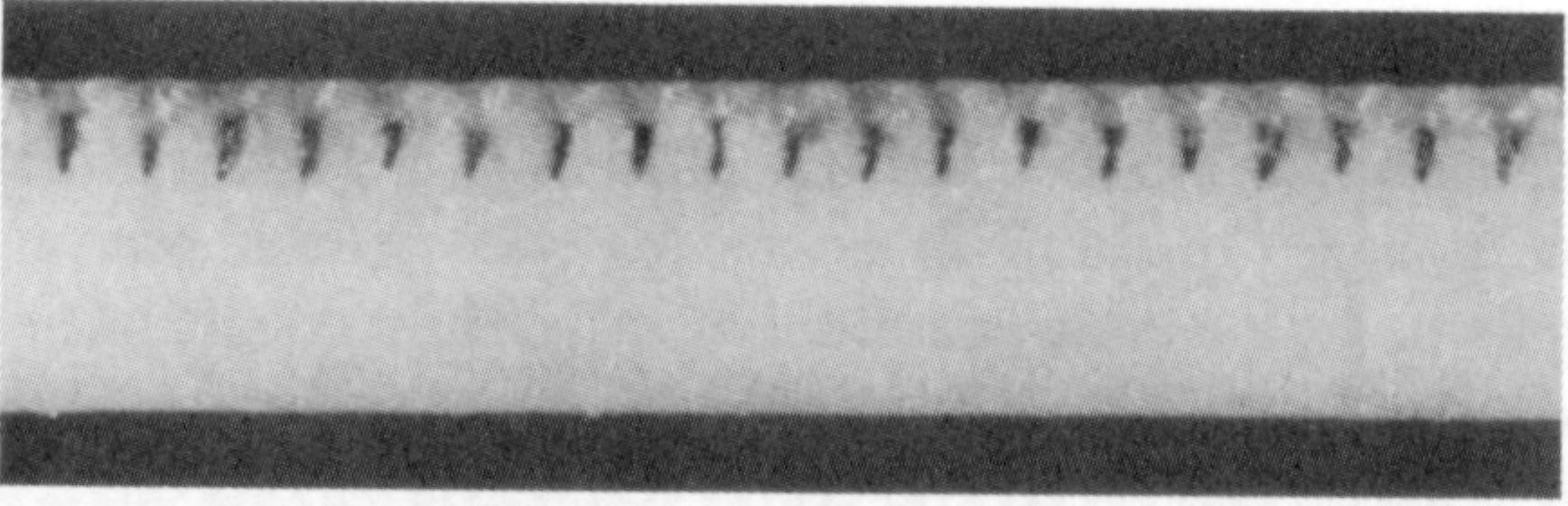
Fig. 5 Laser cut grooves for cooling applications (Courtesy of Coherent, Inc., 1980)
An alternative method for laser scribing for producing snap lines is proposed in Steen and Kamulu (1983) and Chryssolouris (1988). Using a CW CO2 laser, the laser beam was used to either heat or rnelt a line on the surface of the workpiece. The rapid heating causes micro-crack formation along the line, and the workpiece can be separated by applying a bending torque. One disadvantage of this process is that impurities in the material will cause propagation of cracks outside the line, which will affect the straightness of the snapline. The advantage is that high scanning velocities can be used.
Three-dimensional laser machining:
A new approach has recently been developed for three-dimensional laser machining. The two-beam laser machining concept can be used to perform turning and miring operations on difficult-to-machine materials such as aluminum oxide and silicon nitride (Chryssolouris, 1988). With this method only a small portion of the total volume is removed through melting; the majority of material is removed in the form of chips. Therefore, the energy efficiency of the process in terms of the volume of material removed per unit of energy expended is significantly better than that for other non- traditional machining processes. Also, this process produces three-dimensional geometries such as threaded or curved surfaces which are difficult to reproduce with mechanical processes. Due to the hardness and brittleness of most ceramics, mechanical machining processes usually result in a significant amount of tool wear, which increases the manufacturing cost of the part. Since the laser machining process does not involve contact between the tool and workpiece, there is no tool wear or tool breakage.
During the laser machining process, molten material is ejected from the grooves with the aid of supersonic off-axial gas jets. Similar to three-dimensional laser machining of metals, high energy densities and multiple beam passes are required for chip removal in ceramics. A single-beam pocket cutting technique can be used to remove a volurm of material through selective melting or vaporization with a laser bearm. By Affolter and Schmid (1987), a 0.7mm deep pocket was machined in silicon nitride by machining overlapping grooves with the laser beam perpendicular to the workpiece surface. By Copley et.al.,(1983), a single-beam technique for creating three-dimensional contours is presented, a 450W CW CO2 laser was used to machine overlapping grooves on a ceramic workpiece in order to remove a volume of material. Silicon carbide, silicon nitride, alumina, and SiAlON were tested. The beam was directed tangentially to the workpiece surface in order to create a groove. In the study, the surface roughness of the finished part was controlled by decreasing the groove depth on successive overlapping passes. This technique was used to produce flat or threaded surfaces on a workpiece. The process described in Copley et.al.,(1983) is analogous to electra-discharge machining (EDM) processes, since beam energy must be used to melt or vaporize the entire material volume to be removed. Material removal rates can be increased by using a N2 or O2 gas jet for reactive gas cutting.
![]()
![]()
![]()
