![]()
![]()
S3.6 Thick section laser cutting
Thin section laser cutting has been widely accepted by industry as being a highly adaptable and accurate means of processing for metals. However, the upper limit of the commercially viable process is around 15mm thick. Laser job shops are frequently asked to cut metals above this thickness but due to poor understanding of the process kinetics, above this range the cut quality is poor. Edge striations and bottom attachments increase with cutting thickness, sideway burning may become very serious. Normally, the cutting speed reduces rapidly when cutting mild steel above 10mm thick, cutting speeds can be much slower than one 1.0 centimeter per second, and reproducibility of the cuts are usually below acceptable thresholds and can not compete with conventional techniques (O'Neill, 1992).
Fisrt let's examine why thin section and thick section laser cutting are so different, then we will review the progresses in this direction.
The main reason for the break down of thick section laser cutting is due to the increase in thermal losses from the cut zone as the cutting speed is decreased. The most substantial thermal loss from the cut zone is by conduction. The levels of conductive loss rise rapidly with increasing material thickness, and this results in the drop of cutting speed. The removal of material from the bottom of the cut becomes inconsistent. Even though the beam passes through the plate, large amounts of dross accumulates on the underside of the plate. The dross attachment is due to the low average temperature of the melt compared with that created in thinner sections. The reduction in temperature is a result of the larger energy "wasted" in thick section cutting processes. A second pass is often used to separate the dross before the part can be extracted (Powell, 1992).
Another reason for low speed in thick section cutting is that we must limit the sideway burning to an acceptable level. When the area surrounding the cut zone reaches the temperature at which it can ignite in the oxygen stream, a widespread reaction takes place. Often sideway burning occurs at the top edge, so much lower pressure of oxygen is used to prevent burning on the top edge. The thicker the material, the narrower the range of the oxygen pressure--about 10psi compared with 30-50psi in thin sections (Ilavarasan, 1995). This reduces the oxidation at the lower edges, as a result, the capability of the melt removal is lowered.
We know in oxygen laser cutting of mild steel, oxidation plays an important role. The laser beam creates a "key hole" into the workpiece. The hole is surrounded by oxidized molten metal which closes the hole when the beam travels in the cutting direction. Since the oxygen impurities have strong influence on the laser cutting process, inability to provide sufficient energy at the lower reaches of the cut to produce a highly fluidised melt results in lower cutting speed and lower quality.
The third reason is the difference of geometries. The inclination of molten front becomes prominent in thick section laser cutting, this will reduce the absorption of the laser power and further reduce the cutting speed.
Finally, the depth of focus of the laser beam must be big enough to maintain high laser intensities throughout the depth of cut. This adds strict requirements on the beam modes and qualities if satisfactory cutting is to be achieved in thick section case. This surely adds more difficulties in thick section high speed cutting.
But substantial progress has been made in thick section high speed laser cutting. Let's do some literature review here.
Quality of cutting edge of thick steel plate cut by CO2 laser was addressed by Kanaoka, Masaru(1991). He found that for plates thicker than 9 mm, as the cutting speed decreases, the difference between the cutting speed and the oxidizing reaction speed produces rougher edge. Therefore, CO2 laser cutting cannot provide versatility over a wide range of thick plate applications. Using high-frequency, low-duty pulses the groove size produced by the oxidizing reaction is reduced. Moreover, a beam energy of higher peak power can be transmitted through a greater thickness than possible during CW cutting.
The special problem of beam quality in high power CO2 lasers was addressed (Fukaya, Kuniaki and Karube, Norio, 1991). It is observed that the beam does not obey optical formula that are valid in lower power situations. This is particularly true with the beams of low order mode and power greater than 2 kW. Traditional approaches aimed at improving focussing characteristics of such beams may actually produce the opposite effect. The distortion that takes place in the focussing lens has been found to cause serious deterioration of its focussing property. A beam mode that offers good focusing while avoiding the occurence of distortion was pursued theoretically. As a result of this analysis it can be demonstrated that a 2 kW CO2 beam can cut up to 20 mm thick mild steel with good surface quality.
A dual-beam technique involving two CO2 gas lasers with a power capacity of 1.5 kW each, was used to cut steel and superalloy (Molian, P.A., 1993). A comparison with single-beam CO2 laser cutting showed that dual beams were capable of enhancing the cutting thickness and speed without deteriorating the quality of cut. Heat-conduction models, assuming the laser beams as line sources, were used to estimate the cutting thickness and speed as a function of distance between the two laser beams. For mild steel, cutting speed from 10in/min to 90in/min, thickness from 0.25in to 0.75in; for superalloy, speed from 20in/min to 60in/min, thickness from 0.25in to 0.625in were demonstrated.
An off-axial gas jet has been developed that has the potential to extend the laser's effectiveness by improving the rate at which parts can be machined, producing high-quality surfaces, enhancing the cutting thickness, and adding to the range of materials that can be machined (Ilavarasan, P.M., Molian, P.A., 1995). In laser cutting, an erosion front (liquid-gas region) forms at the momentary end of the cut. Laser heating, exothermic reactions and shear force between the gas flow and the molten layer dictate the material removal rates. The principle of the off-axial gas jet is to provide straight, nonturbulent flow to the cutting erosion front, causing further oxidation reactions and transferring momentum to the molten slag and dross, thereby improving the cutting speed and the quality of cut.
A simple mathematical model of thick-section stainless steel cutting with a high power chemical oxygen-iodine laser (COIL) is presented and compared with experimental results obtained with a 10-kilowatt COIL at the U.S. Air Force's Phillips Laboratory (Kar, et al., 1996). This model uses a lumped-parameter technique to relate the cutting kerf depth with various process parameters and can be used to predict scaled laser materials processing performance to very thick sections. The effects of various process parameters such as laser power, spot size and dimensions, and processing speed in the cutting depth are discussed and demonstrated. Finally, the ramifications of this model on thick-section processing of metals are presented, with emphasis on potential applications of COIL to high-speed, thick stainless steel cutting.
The capacities of the pulsed YAG laser thick cutting on metallic material and comparison with the CO2 laser capacities were studied (Alfille, et al., 1996). Stainless steel cutting tests were made in air and underwater using CO2 and YAG lasers. A performance assessment was made for each laser, the wastes produced in the cutting operation were measured and the gases and the aerosols analyzed. Their results showed that the pulsed YAG laser is high performance tool for thick cutting and particularly attractive for nuclear applications
A major problem in laser cutting of thick steel is the removal of the molten material from the kerf. If the oxygen pressure is too low the resolidification of metal or dross on the metal occurs. If the oxygen pressure is too high a burn-out of the cut edges results. In order to understand the burn-out phenomenon better a new approach was adopted to describe the gas flow at the cutting front using the Prandtl boundary flow theory (Heidenreich, et al., 1996). This model provides upper and lower limits for gas velocity and kerf width as a function of sheet thickness in order to guarantee stable melt ejection and controlled metal burning.
Adaptive optics is used to laser cut thicknesses up to 16 mm in mild steel without decrease of the cut surface with a thickness increase. This technique differs from conventional laser beam cutting by the fact that the focus position oscillates several millimetres in the direction of the sheet thickness. The focus shift results in a change of focus length of the adaptive optics which is part of the focusing optics system. A periodic change of the focussing length together with the superposition of a relative movement between the tool and the workpiece causes a sine-shaped path of the focus through the workpiece. This oscillating focus position influences the cutting process and provides a better quality of the cut and higher performances (Geiger, et al., 1996).
So far thick plates of mild steel cannot have been cut with conventional methods unless high power laser is used, but cutting thick plates with 2 kW laser has been developed(Arai, and Riches, 1997). A cutting experiment using a spinning laser beam method was conducted, the maximum cutting thickness was increased sharply, and the cutting speed and gas consumption were improved substantially, especially for stainless steel.
Some recent results of thick section laser cutting are shown in following.
Thick section cutting of stainless steel, Inconel and large grain titanium has been demonstrated with a high brightness diode-pumped solid state Nd:YAG laser (Jones and Chen, 1999). The laser delivers 2KW of pulsed energy to the work surface at 400Hz. These thick section cuts were achieved with high and low pressure assist gas. The thick section cuts show narrow kerfs that are similar to the narrow kerfs observed with wire electric discharge machining(EDM). The following table shows how cutting speeds vary with thickness for 304L stainless steel and Iconel 600 at 2KW.
Cutting speed varies with thickness for 304L stainless steel and Iconel 600 at 2KW.
| Thickness (mm) | Cutting speed for 304L stainless steel(mm/s) | Cutting speed for Iconel 600(mm/s) |
| 12.7 | 9.73 | 6.77 |
| 15.9 | 6.77 | 5.08 |
| 19.1 | 3.38 | 2.54 |
| 25.4 | 1.02 | 1.02 |
| 38.1 | 0.102 | 0.102 |
Figure 3.16 (a) shows a cross section of a high brightness laser cutting of 12.7mm thick Inconel 600. There is dross on the bottom of the cut. Figure 3.16 (b) shows a cross section of a high brightness laser cut of 25.4 mm thick 304L stainless steel with argon assist gas (Marshall Jones and Xiangli Chen, 1999). The sample was cut at a maximum speed of 9.73 mm/s, 2KW 400Hz and a 250mm focal length lens, theassist gas was argon at 18 atmospheres with a nozzle standoff of 1.5mm. There was little evidence of either dross on the back surface or undercutting on the top surface, the HAZ was quite small, the kerf remained relatively constant through the thickness of the sample. The maximum thickness that could be cut with 2KW was 38.1 mm which was similar to Inconel 600.
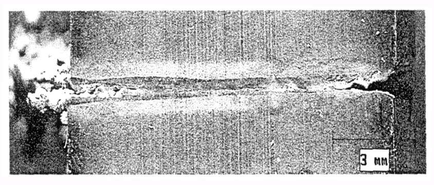
Figure 3.16 (a)A cross section of laser cutting of 12.7mm thick Inconel 600. There is dross on the bottom of the cut(Marshall Jones and Xiangli Chen, 1999)
Figure 3.16 (b) A cross section of a high brightness laser cut of 25.4 mm thick 304L stainless steel with argon assist gas(Marshall Jones and Xiangli Chen, 1999)
One large advantage of Nd:YAG laser beam is easy beam-delivery with an optical fiber. By using this advantage, application area of Nd:YAG laser beam spreads widely. One area is the outside of workshops, for example, a construction spot where people can not approach, a disaster spot and an operation under water. Cutting technology of thick steel with fiber-delivered high power Nd:YAG laser beam of 3.8 kW or more in output power was developed recently (Watanabe, et al., 1999). Used materials were mild steel (SS400) and stainless steel (SUS304) of 50 mm in thickness. Oxygen gas, nitrogen gas and dry air were used as an assist gas. Obtained results were summarized as follows. (1) When oxygen gas was used as the assist gas, the kerf width at lower part of the plate was wider than one at higher part because of self-burning. However, the kerf width was almost uniform at both of the upper and the lower parts of the plate in case of dry air assist. (2) The kerf width decreased rapidly with increasing cutting speed. (3) When oxygen gas was used as assist gas, the maximum cutting speeds in mild steel and stainless steel of 50 mm thick plate were 200 mm/min and 50 mm/min respectively. Figure 3.16 (c) and (d) show the results of thick section cutting using Nd:YAG laser.
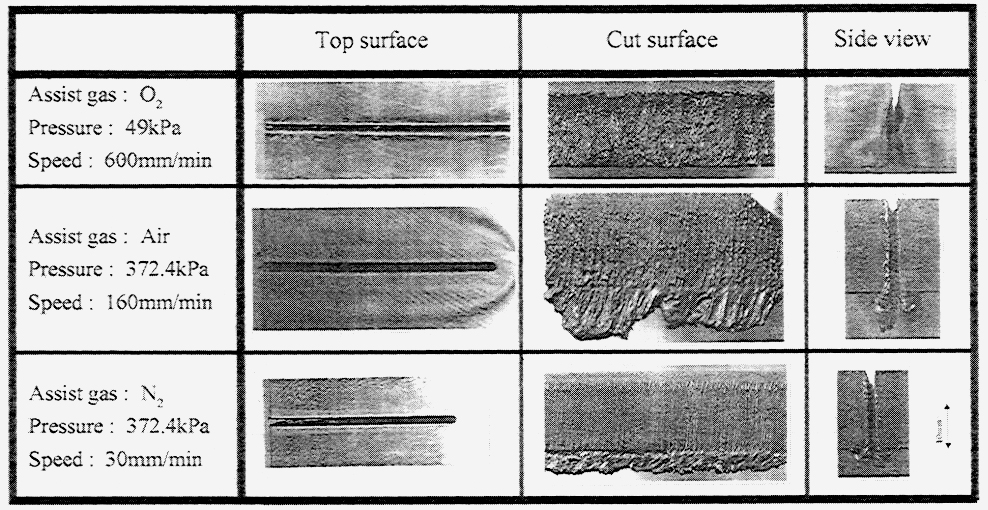
Figure 3.16 (c)Laser cutting of 20mm-thick stainless steel, fiber-delivered high power Nd:YAG laser (Watanabe, Takehiro, et al., 1999)
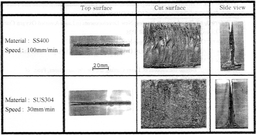
Figure 3.16 (d) Laser cutting of 50mm-thick mild steel, fiber-delivered high power Nd:YAG laser (Watanabe, Takehiro, et al., 1999)
A series of laser cutting experiments performed on a 2" thick steel cross section using 100-kW CO2 flattop laser was reported recently(Robert J. Hull and Michael L. Lander, 2000). The results was shown in Figure 3.16(e) and (f). At an intensity -on-target level of 60kW/cm2, the steel sample could be cut through at a rate of 15.75 inch/min, at intensities as low as 30kW/cm2, the sample could be cut through at a speed of 9 inch/min. Laser cutting of such thickness steel proved to be environmentally cleaner than other methods.
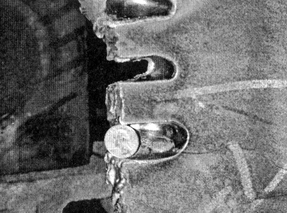
Figure 3.16 (e) Front view of 100 KW CO2 laser cutting of 50.8 mm-thick structural steel, spot size= 1.45cm. A quarter is put into the kerf. (Robert J. Hull, et al., 2000)
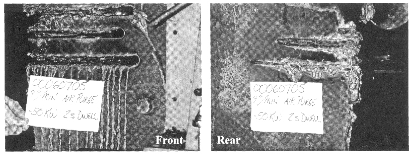
Figure 3.16 (f) Front and rear views of 50 KW CO2 laser cutting of 50.8mm-thick structural steel (Robert J. Hull, et al., 2000)
From above review we see that various aspects for improving thick section cutting were studied. Laser source, beam quality, gas jet are the three major factors. Modeling of thick section cutting must consider the complexities we mentioned in above.
References:
Kanaoka, Masaru, 1991, "Quality of cutting edge of thick steel plate cut by CO2 laser," Nippon Kikai Gakkai Ronbunshu, C Hen/Transactions of the Japan Society of Mechanical Engineers, Part C v 57 n 539 Jul 1991, pp. 2441-2446
Fukaya, Kuniaki and Karube, Norio, 1991, "Analysis of CO2 laser beam suitable for thick metal cutting," LIA (Laser Institute of America) v 71 Nov 4-9 1990 1991 pp. 61-70
O'Neill W., Gabzdyl. J. T. and Steen W. M., 1992, "The dynamical behaviour of gas jets in laser cutting", ICALEO'92, pp449-458.
Powell J., 1992, "CO2 laser cutting", Springer-Verlag, 1992.
Molian, P.A.,1993, "Dual-beam CO2 laser cutting of thick metallic materials," Journal of Materials Science, Vol. 28 No.7, Apr 1 1993, pp 1738-1748.
Ilavarasan, P.M., Molian, P.A., 1995, "Laser cutting of thick sectioned steels using gas flow impingement on the erosion front," Journal of Laser Applications, Vol. 7 No. 4, Dec 1995, pp. 199-209
Kar, A., Scott, J.E. and Latham, W.P., 1996," Theoretical and experimental studies of thick-section cutting with a chemical oxygen-iodine laser (COIL) ", Journal of Laser Applications Vol.8 No. 3, Jun 1996, pp. 125-133
Alfille, J.P., Pilot, G. and De Prunele, D., 1996, "New pulsed YAG laser performances in cutting thick metallic materials for nuclear applications," Proceedings of SPIE - The International Society for Optical Engineering v 2789 Jun 10 1996, pp. 134-144
Heidenreich, B., Jueptner, W. and Sepold, G.,1996, "Fundamental investigations of the burn-out phenomenon of laser cut edges," Lasers in Engineering, Vol.5 No.1, 1996, pp. 1-10.
Hull, Robert J. et al., 2000, "Experiments in Laser Cutting of Thick Steel Sections Using a 100-kW Co2 Laser," ICALEO 2000 Laser Materials Processing, Vol. 89, pp. B78-86.
Geiger, M., Schuberth, S. and Hutfless, J., 1996, "CO2 laser beam sawing of thick sheet metal with adaptive optics," Welding in the World, Le Soudage Dans Le Monde 37 1 Jan-Feb 1996, pp. 5-11
Arai, Takeji and Riches, Steve, 1997, "Thick plate cutting with spinning laser beam," Laser Institute of America, Proceedings v 83 n Pt 1, Nov, 1997. pp. B19-B26
Watanabe, Takehiro; Kobayashi, Hiroyuki ;Suzuki, Keiji and Beppu, Seiji,1999, "Cutting of thick steel with fiber-delivered high power Nd:YAG laser beam," Proceedings of SPIE, Vol. 3888 Nov 1-Nov 5 1999, pp. 635-642
Marshall Jones and Xiangli Chen, 1999, "Thick section cutting with a high brightness solid state laser," ICALEO 1999, Section A pp.158-165.
There are many other progresses in LMP we do not cover here, these directions include high aspect ratio hole drilling, short pulse and ultrashort pulse laser machining, machining of advanced materials, 3D laser machining, abrasive laser machining, etc. Because of time limitations, we have to stop here at level 1 of chapter 3. Interested readers are encouraged to explore LMP by themself. Type in the key words in Compendix or read the proceeding of ICALEO, you will see find the relevent information.
Congradualations! You have reached the end of chapter 3, level one. Please do the following chapter quiz, then move on to next chapter, or you can jump to Level Two of this chapter for deeper understanding of Energy Transfer and Modleing.
![]()
![]()