![]()
![]()
Cross Process Innovations
Section 6. Laser Shock Processing and Underwater Laser Machining
![]()
![]()
Cross Process Innovations
Section 6. Laser Shock Processing and Underwater Laser Machining
1. INTRODUCTION
In laser materials processing such as laser machining/micromachining, target material inevitably undergoes intensive non-uniform temperature changes and as a result a complex residual stress distribution forms near the processed area. An unfavorable stress distribution may result in microcrack formation and propagation, reduce the part’s fatigue life, and lead to catastrophic failures. For this reason, studies were carried out to investigate such process effects.
Thermally induced stress in laser drilling and scribing of ceramics was studied (Modest, 1997; Modest and Thomas, 1999). Their simulations show that there exists a very thin region of compressive residual stress at the surface of the hole, while substantial tensile stresses develop over a thick layer below and parallel to the surface. Numerical analysis of the heat affected zone and residual stress distributions for laser cutting of stainless steel was investigated (Li and Sheng, 1995; Sheng and Joshi, 1995). Their simulation results based on an in-plane model show that along the cutting edge there is a high level of tensile stress that sharply reverts to compressive stress once away from the edge. The sharp stress gradient was thought to make the cutting edge susceptible to micro/macro crack formation.
If such processes can be altered in some fashion, one will have control over the resultant residual stress distribution at least to some extent. Laser shock processing (LSP) may potentially offer the possibility of doing so. LSP has been studied on and off since 1970s (Clauer, et al., 1981; Peyre, et al., 1996), in which laser generated shock waves in a confining medium are used to improve the mechanical properties of metallic materials including aluminum, steel and copper alloys. In particular, LSP induces compressive residual stress in the target and improves its fatigue life. Lasers of 1.06 mm wavelength and 1-6 mm beam size are commonly used in conventional LSP.
In this session, basic principles and some
modeling aspects of LSP are briefly explained followed by discussions on possible
introduction of the LSP effects into laser micromaching processes.
Experimental and numerical considerations are then given.
In the section on results and discussion, experimental validation of
the LSP simulation model is first reported, the resultant residual stress
distribution is discussed, and the simulation is extended to pre-drilled,
pre-grooved target geometry. Finally,
laser micromachining experiments aimed at having the LSP effects are carried
out to demonstrate the feasibility of such introduction.
2. BASIC PRINCIPLES OF LASER SHOCK PROCESSING
In order to investigate possible introduction of the effect of LSP in laser machining/micromaching processes, the basic principles of LSP are briefly explained below. As illustrated by Fig. 35, when a short and intense (>1 GW/cm2) laser pulse is irradiated onto a metallic target, the surface layer instantaneously vaporizes into a high temperature and high pressure (~1-10 GPa) plasma. This plasma induces shock waves during expansion from the irradiated surface, and mechanical impulses are transferred to the target. If the plasma is not confined, i.e., in open air, the pressure can only reach several tenths of one GPa. If it is confined by a liquid (e.g., water) or another type of medium, the shock pressure can be magnified by a factor of 5 or more compared with the open-air condition (Fox, 1974). At the same time, the shock pressure lasts 2 to 3 times longer than the laser pulse duration. Most LSPs also use a coating to protect the target from thermal effects so that nearly pure mechanical effects are induced. The coating could be metallic foil, organic paints or adhesives. These coatings can modify the surface loading transmitted to the substrate by acoustic impedance mismatch effects at the coating-substrate interface, and an additional 50% increase in the peak stress values can be achieved (Peyre, et al., 1998). Pressures above 1 GPa are above the yield stress of most metals, thus plastic deformation can be induced. If the peak shock pressure is over the HEL (Hugoniot Elastic Limit) of the target material for a suitable time duration, compressive stress distribution in the irradiated volume can be formed (Clauer, et al., 1981). The beam spot size used was in the order of millimeters and the compressive stress typically reached about one millimeter into the target material.
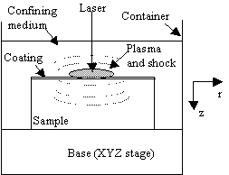
Fig. 35 Illustration of LSP
3. MODELING ASPECTS
OF LASER SHOCK PROCESSING
In LSP, the target is subjected to strong shock pressures
(typically >1 GPa), the interaction time is short (<100 ns), and the
strain rate is high (>105 s-1). As a result, some aspects
of modeling are briefly discussed below.
The changes necessary for the micro scale of interest in this paper, are
also explained.
3.1 Shock pressure
Earlier modeling work on laser-induced shock waves was carried out by Clauer, et al. (1981). Their model considered the non-linear coupled irradiation and hydrodynamic equations governing pressure evolution at the metal surface. Fabbro, et al. (1990) developed a model, which assumes that the laser irradiation is uniform and therefore shock propagation in the confining medium and the target as well is one-dimensional. The 1-D assumption is appropriate when the size of laser beam, which typically follows a Gaussian distribution, is relatively large. The shock model in this paper made modifications to Fabbro's model assuming the laser beam spot size is in the order of microns. The 1-D assumption is followed but a 2-D equivalence is considered to account for the small laser spot size.
In LSP, a portion of the incident laser intensity I(t) is absorbed by the plasma as ![]() where AP(t) is the absorption coefficient of
the plasma. Assuming a constant
fraction a of the absorbed
energy be used to increase the thermal energy of the plasma, the following
relations between shock pressure P(t)
and plasma thickness L(t) can be derived
(Fabbro, et al., 1990):
where AP(t) is the absorption coefficient of
the plasma. Assuming a constant
fraction a of the absorbed
energy be used to increase the thermal energy of the plasma, the following
relations between shock pressure P(t)
and plasma thickness L(t) can be derived
(Fabbro, et al., 1990):
![]() (1)
(1)
![]() (2)
(2)
where ![]() is the impedance expressed in terms of those of the confining
medium (Z1) and the target material (Z2). The impedance is the product of density r and shock propagation velocity D. For instance, the impedance
of aluminum, copper and water are 1.5´107 kg/m2s,
4.18´107
kg/m2s, and 1.65´106 kg/m2s, respectively.
is the impedance expressed in terms of those of the confining
medium (Z1) and the target material (Z2). The impedance is the product of density r and shock propagation velocity D. For instance, the impedance
of aluminum, copper and water are 1.5´107 kg/m2s,
4.18´107
kg/m2s, and 1.65´106 kg/m2s, respectively.
If I(t), AP(t) and a are constants, shock pressure is found to be proportional to the square root of laser intensity. If I(t), AP(t) and a are variables, the peak shock pressure is still proportional to the square root of the peak laser intensity and a. Thus it is reasonable to assume that shock pressure follows a Gaussian spatial distribution with its 1/e2 radius proportional to the1/e2 radius of the laser beam. In this way, spatial non-uniformity of shock pressure is considered, which is needed when the laser spot size is small as in this case. The spatially uniform shock pressure P(t) relates to the spatially non-uniform shock pressure as
![]() (3)
(3)
where r is the radial distance from the center of the laser beam, and r0 the radius of laser beam. P(r,t) can be solved numerically from the above equations given initial values of P(t) and L(t). The values of P(r,t) are then used as dynamic shock load in the subsequent stress analysis. A typical dependence relationship of the shock pressure magnitude and duration on laser intensity is shown in Fig. 36.
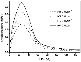
Figure 36 Effects of laser intensity on shock pressure (pulse duration = 50ns and a = 0.2) for water-confined aluminum.
3.2 Stress analysis
The governing equations for stress analysis follow standard elasticity/plasticity analysis except the extremely high pressure and strain rate involved calls for special considerations. The influence of the high strain rate on the yield strength of material has been considered (Meyer, 1992; Johnson, et al., 1983). The influence of pressure on the yield strength of material was found to be more important than other effects when the pressure is larger than 10 GPa and a constitutive model applicable to such high pressures was given by Steinberg, et al. (1980). Steinberg's model did not consider rate dependent effects, however. For shock pressures below 10 GPa, the rate dependent effects cannot be neglected (Zhang and Yao, 2000). In laser shock processing, the pressure involved is fairly high (>1 GPa) but less than 10 GPa. Therefore, both strain rate effects and shock pressure effects on the yield stress of materials need to be considered. Based on the above mentioned models and assuming that the material compression is negligible in the range of working pressure (below 10 GPa), the following constitutive equations are suggested and used in this paper.
![]() (4a)
(4a)
![]() (4b)
(4b)
![]() (4c)
(4c)
where G is the shear modulus, P
is pressure, T is temperature, Y is yield strength, Y0 and G0
are values at reference state (T =
300 K, P = 1 atm, strain free),
C is the logarithmic rate sensitivity at
strain rate 1 s-1, e
is strain, ![]() is strain rate, B and n are the material parameters describing work hardening effect.
The primes in Eq. 4 denote derivative with respect to the quantity indicated
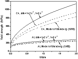
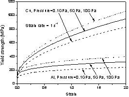
in the subscribt. As seen from Fig.
37, the influence of high strain rate and high pressure on the yield strength
of copper and aluminum is significant (Zhang and Yao, 2000).
is strain rate, B and n are the material parameters describing work hardening effect.
The primes in Eq. 4 denote derivative with respect to the quantity indicated
in the subscribt. As seen from Fig.
37, the influence of high strain rate and high pressure on the yield strength
of copper and aluminum is significant (Zhang and Yao, 2000).
(a)
(b)
Figure 37 (a) Influence of strain
rate on the yield strength of copper and aluminum (pressure = 1 atm and T = 300 K); and (b) Influence of ultrahigh
pressure on the yield strength of copper and aluminum (strain rate = 1 s-1
and T = 300 K)
4.
CONSIDERATIONS IN INTRODUCING THE LSP EFFECT TO LASER MACHINING / MICROMACHINING
PROCESSES
If a laser machining/micromachining process
is carried out in a confining medium (e.g., water), it may realize the effect
of LSP, that is, imparting compressive residual stress into the target material
as explained in Section 2. In fact,
laser machining underwater or in other liquids were investigated (Watu, et
al., 1993; Alfille, 1996). Advantages
such as reduced heat-affected zone, reduced debris re-deposition, and beam
self-focusing were reported. But the effect of LSP was not observed. This is because the laser intensity used in
these studies was not high enough to induce the shock waves as in LSP. If a suitably higher intensity is employed,
it is possible to introduce the LSP effect into a laser machining/micromaching
process confined in water.
On the other hand, overly high laser intensity
may cause water breakdown. When water
breakdown takes place, laser energy cannot reach the target surface efficiently
and water will lose its function of confinement. The exact level of laser intensity causing
water breakdown depends on laser wavelength and the laser-water interaction
time. When the laser pulse duration
is in the order of nanoseconds, water can stand fairly high level of laser
intensity without breakdown, for instance, in the order of 4 GW/cm2
for laser wavelength of 355 nm (Berthe, et al., 1999).
For LSP alone, the number of pulses required usually ranges from one to a very few and the pulse duration used is normally short. If a laser machining/micromachining process employs a pulsed laser source with pulse width in the nanosecond scale and a slow repetition rate, it is perceivably possible to raise the laser intensity to machine and shock process at the same time. The slow repetition rate is required to prevent possible severe water breakdown. But in practice, laser machining/micromachining is usually carried out in either pulse mode with a high repetition rate or in continuous wave mode in order to obtain a reasonable material removal rate.
Another possibility is to carry out laser machining and shock processing sequentially, that is, to apply LSP to a pre-machined part. The part could be machined using laser or other means and has an undesirable residual stress distribution around the machined region. LSP is then used to impart additional stress to result in a more desirable residual stress distribution.
Whether to machine and shock process simultaneously (using a
pulsed laser with pulse width in the nanosecond scale) or sequentially, a
coating may or may not be applied. With
a coating, the shock effect could be enhanced as discussed earlier. But under the simultaneous machining/shock
processing scheme, the benefit of the coating will be realized only during the
first few pulses. Once the coating is
vaporized, only the confining water helps enhance the shock waves. On the other hand, coating is inconvenient
in machining especially in industrial settings and therefore a good compromise
perhaps is to use no coating in the simultaneous machine/shock process. Under the sequential machining/shock
processing scheme, a coating could be used in the shock-processing phase. But the benefit of enhancing shock waves may
be offset by the fact that it is inconvenient to coat the pre-machined features
and it becomes more difficult to clean the residual coating around these
features after shock processing.
5. EXPERIMENT AND SIMULATION
LSP experiments were first carried out to validate LSP simulation results. Experiments were then extended to laser drilling and grooving confined by water with and without coating. Copper foil of 90-micron thickness and aluminum foil of 70-micron thickness were used as target materials. The foils were made into 10 by 10 mm samples, each of which was adhesively attached to a stainless steel back for rigid support and easy handling. To apply the coating, a thin layer of high vacuum grease (about 10 microns) was spread evenly on the polished sample surface, and the coating material, aluminum foil 16 microns thick, which was chosen for its relatively low threshold of vaporization, was tightly pressed onto the grease. The sample was placed in a shallow container with distilled water around 3mm above the sample (Fig. 35). A frequency tripled Nd:YAG laser in TEM00 mode was used (wavelength 355 mm), laser pulse duration was 50 ns, laser repetition rate is 1KHz, and laser beam size is 12 microns. Pulse energy was varied from 160 mJ to 240 mJ corresponding to laser intensity of 2.83 to 4.24 GW/cm2. After shock processing, the coating layer and the vacuum grease were removed. The geometry of the shocked area was observed using optical microscope, SEM and profilormeter.
LSP simulations were carried out. In the stress analysis, work hardening, strain rate and pressure effects on yield strength (Eq. 4) were considered at room temperature. This is reasonable because only the coating is vaporized and minimal thermal effects are felt by the sample. Shock pressure was computed and used as loading for the 2D axisymmetric stress analysis. A commercial FEM code, ABAQUS, was used to compute the deformation and stress distribution of the sample under the shock pressure. The computation domain is 70 (90) microns in z-direction and 1000 microns in r-direction for the aluminum (copper) sample (Fig. 35). The radial (11) and depth (22) directions used in Figs. 7 and 9 are defined in Fig. 35. The mesh is denser near the center and the top. The simulation is a dynamic implicit nonlinear process. Single and multiple pulses at various energy levels were simulated. The boundary conditions for the axisymmetric stress model are as follows. At the centerline, dr = 0 due to symmetry where dr is the r-axis displacement; at the outer edge, traction free, that is sijnj = 0, i, j = r, z; at the bottom surface, fixed in position, that is, dz = 0, dr = 0 and dz is the z-axis displacement; and at the top surface, surface traction equals the applied shock pressure, that is, sijnj = P(r,t), i, j = r, z.
LSP of samples with a pre-drilled hole on the top surface was
also simulated to examine the effects of shock pressure on the stress distribution
around the hole. Thermal effects were
again neglected under this sequential machining/shock processing scheme. The computation domain is the same as the
above except that a blind hole (radius = 10 mm, depth = 20 mm)
was assumed at the top surface coaxial with the symmetrical axis. At the bottom of the hole and the top surface
of the sample, surface traction equals the applied shock pressure, that is, sijnj = P(r,t), i, j = r, z. At the wall of the
hole, sijni
= P(r=10 mm, t), i, j = r, z, because of the blindness of the hole. The other boundary conditions are the same as above.
6. RESULTS AND DISCUSSIONS
6.1 Experimental validations of LSP modeling
Fig. 38 shows a typical SEM micrograph of
dents made on aluminum surface using LSP. Each dent was produced by 3 laser
pulses with pulse energy E=240 mJ (I=4.24 GW/cm2). The holes shown on both sides of the figure
were drilled for locating purpose. Fig.
39 shows the SEM micrograph of dents made on copper surface using LSP under
the same condition. Note the difference
in magnification and the dents on aluminum in fact are much larger and deeper
than that on copper due to the lower yield strength of aluminum (Fig. 37). As seen, the dents are quite visible under
the SEM and are evidence of plastic deformation.
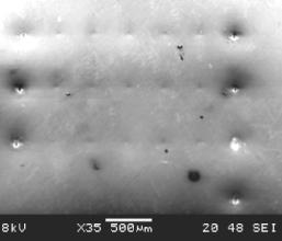
Figure 38 SEM micrograph of dents
produced by LSP on aluminum sample (3 laser pulses at each location with pulse
energy E = 240 mJ, laser
pulse duration = 50 ns, pulse repetition rate = 1 KHz, beam diameter = 12
microns, laser wavelength = 355 nm)
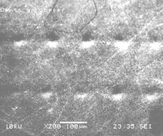
Figure 39 SEM micrograph of dents
produced by LSP on copper sample (under the same condition as stated in Fig.
4)
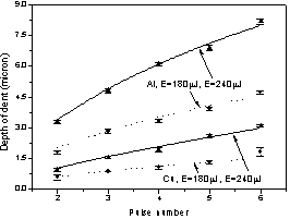
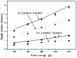
The geometry of the dents was measured using
a profilometer and compared with simulation results. Comparison between experiments
and simulations in terms of dent depth is shown in Fig. 6. As mentioned, aluminum has larger deformations
than copper given the same process condition because aluminum’s yield strength
is lower. As the pulse number increases
from 2 to 6 the dent depth increases almost linearly (Fig. 6 (a)).
This is due to the fact that subsequent pulses see almost the same
geometry on the target as previous ones since the deformation is small.
On the other hand, when pulse energy increases the increase of the
dent depth is faster (Fig. 6 (b)). This is because when the pulse energy increases,
both the level of shock pressure and the duration of the pressure increase
as seen in Fig. 2. The relatively
large deviations at 5 to 6 pulses were due to thermal effects because the
coating layer was too thin to totally isolate the thermal effects when the
number of pulses increases.
In general, experimental results agree well
with simulation predictions for both aluminum and copper under various conditions.
(a)
(b)
Figure 40 Geometry comparison
between experiments and simulations for copper (thickness = 90 microns) and
aluminum (thickness =70 microns) (a)
Dent depth vs. pulse number, E =
180 mJ and 240 mJ; and (b) Dent depth
vs. pulse energy, pulse number = 2 and 3.
The error bars represent standard error.
6.2 Residual stress
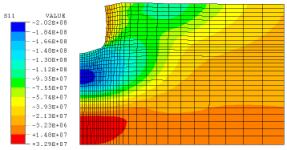
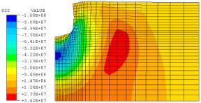
Fig. 41 shows a typical distribution of
residual stresses for a single pulse with pulse energy E = 200 mJ (I = 3.54
GW/cm2). The computation
domain is 70 microns by 1000 microns, and the region shown is 70 microns by
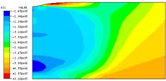
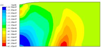
150 microns for viewing clarity of the area heavily stressed. As seen from Fig. 41 (a), radial stress S11 is compressive in a wide region below
the top surface with the maximum of 148 MPa reached along the centerline and
about 60 microns into the sample. On
the top surface, S11 is compressive
within 10 microns from the center and is tensile in the range of 10 to 35
microns, and then becomes compressive again. Such tensile radial stress near the edge of laser irradiation was
also observed in LSP using large beam sizes (Clauer, et al., 1981). This thin layer of tensile stress is undesirable,
but can be altered by overlapping laser pulses at proper spacing as shown
in Fig. 42 (c) where a line of dents were induced by overlapping laser pulses
at a uniform spacing of 25.4 microns. The
wide range of compressive radial stress near the top surface is desired for
the prevention of crack formation and propagation.
(a)
(b)
Figure 41 (a) Radial residual stress S11; and (b) In-depth residual stress S22. Aluminum, E=200 mJ (I=3.54 GW/cm2), AP=0.545, and a=0.2. Computation domain is 70 microns by 1000 microns, and the region shown is 70 microns by 150 microns for viewing clarity. The deformation is magnified by a factor of 3 for viewing clarity. Stress unit: Pascal. The axial directions are as defined in Fig. 35.
6.3
Feasibility study results of introducing LSP effects into laser micromachining
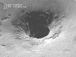
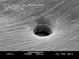
Laser drilling and grooving experiments confined by water were
carried out to explore the feasibility of introducing the LSP effect into
laser micro-machining. Laser beam
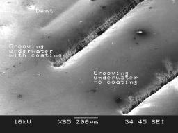
size was 12 microns and Laser intensity was chosen as 4 GW/cm2. Fig. 42(a) and (b) show through-holes drilled
with and without coating on the aluminum sample of 70-micron thickness.
45 laser pulses were used. The area
surrounding
the hole was obviously dented and clearly indicates
surface compression took place as in LSP.
Such dented regions were not observed in open-air or previously reported
underwater laser machining research work.
The hole drilled with coating (Fig. 42(a)) shows stronger denting
than the hole drilled without coating (Fig. 42 (b)) because
of coating-enhanced shock effect, although the hole drilled with coating has
a rougher surface perhaps left there by burnt grease or coating.
of 70-micron thickness.
45 laser pulses were used. The area
surrounding the hole was obviously dented and clearly indicates surface compression
took place as in LSP. Such dented
regions were not observed in open-air or previously reported underwater laser
machining research work. The hole
drilled with coating (Fig. 42(a)) shows stronger denting than the hole drilled
without coating (Fig. 42 (b)) because of coating-enhanced shock effect, although
the hole drilled with coating has a rougher surface perhaps left there by
burnt grease or coating.
Fig. 42(c) shows
the results of laser grooving on aluminum sample of the same thickness. 24 pulses were applied at a location before
the laser beam moved to the next adjacent location 25.4 microns apart. The process was repeated until a groove was
formed. The reason of using this scheme
instead of continuously moving the beam is to prevent continuous interaction
of laser and water and possible water breakdown.
Note the areas around the grooves were visibly dented and again indicate
strong compression took place. Grooving
with coating produced slightly deeper dented area around the groove than grooving
without coating. Compared with open
air drilling and grooving, laser drilling and grooving confined by water at
a proper laser intensity level produced cleaner top surfaces and visibly dented
area around the machined region. This
is indicative of the potential of achieving high quality machining results
along with substantial compressive residual stress distributions by introducing
the LSP effect into laser machining / micromachining.
(a)
(b)
(c)
Figure 42 (a) Laser drilling confined by water with coating; (b) Laser drilling confined by water without coating; and (c) Laser grooving confined by water with and without coating. Aluminum sample thickness = 70 mm. Pulse energy E = 230 mJ (I = 4 GW/cm2), pulse duration = 50 ns, beam diameter = 12 mm. Holes were drilled with 45 pulses. Grooves were formed by a series of holes uniformly spaced at 25.4 mm and each hole was drilled with 24 pulses. Laser pulse repetition rate = 1KHz.
(a)
(b)
Figure 43 Typical distribution
of residual stresses on aluminum sample with a predrilled blind hole (radius
= 10 mm, depth
=20 mm)
(a) radial residual stress S11; and (b) in-depth residual stress S22, E
= 230 mJ
(I = 4 GW/cm2), beam
diameter = 12 mm. Stress unit: Pascal. Axisymmetry is assumed. The region shown is 70 by 100 mm. Deformation
is magnified by a factor of 3 for viewing clarity. (The axial directions are
as defined in Fig. 35)
Simulation
was carried out for LSP of samples with a pre-drilled blind hole to mimic
the sequential machining/shock processing scheme. The boundary conditions and the location and
size of the hole was described in Section 5.
Pulse energy E is 230 mJ, corresponding to the
4 GW/cm2 laser intensity used in experiments of underwater laser
drilling and grooving. Although thermal
effects and initial stresses were not considered, these simulation results
provide preliminary feasibility assessment of the scheme. As seen, under the action of shock pressure,
plas tic deformation was induced around the surface of the hole(Fig. 43). Radial residual stress S11 is compressive around the hole. The compressive region extends 30 microns downward from the bottom
of the hole and 100 microns outward from the centerline (Fig. 43(a)).
Maximum compressive radial residual stress (about –202 MPa) is reached
around 15 microns below the bottom of the hole.
In-depth residual stress is close to zero on the top surface as expected
from the equilibrium requirement, but beneath the bottom of the hole it is
compressive (Fig. 43 (b)). Such residual
stress distribution is desired for the purpose of crack prevention.
7. CONCLUSIONS
Based on a brief review of principles and model of laser shock processing, the possibility of introducing the LSP effect, that is, imparting compressive residual stress distribution into the target material, to laser micromachining processes were discussed and its feasibility were experimentally and numerically investigated. The LSP model was properly modified to suit for the micro scale, and the effects of high strain rate and ultrahigh pressure were considered in the stress analysis. It is shown that both simultaneous and sequential micromachining/shock processing are feasible. Under both schemes, significant compression was observed. Under the simultaneous scheme, it is important to keep the repetition rate of a pulsed laser source low to avoid possible water breakdown but this may impair the material removal rate of the process.
REFERENCES
Alfille, et al., 1996, "New pulsed YAG laser performance in cutting thick metallic materials for nuclear applications," SPIE, 1996, Vol. 2789, pp. 134-144.
Berthe, L., et al., 1999, "Wavelength dependent of laser shock-wave generation in the water-confinement regime," J. Appl. Phys., June, 1999, Vol. 85, pp. 7552-7555.
Clauer, A. H., et al., 1981, "Effects of laser induced shock waves on metals," Shock Waves and High Strain Phenomena in Metals-Concepts and Applications, New York, Plenum, 1981, pp. 675-702
Fabbro, R., et al., 1990, "Physical study of laser-produced plasma in confined geometry," J. Appl. Phys., July, 1990, Vol. 68(2), pp. 775-784.
Fox, J. A., 1974," Effect of water and paint coatings on laser-irradiated targets," Appl. Phys. Lett., 15 May 1974, Vol.24, No. 10, pp. 461-464.
Johnson, G. R., et al., "Response of various metals to large torsional strain over a large range of strain rates," J. Eng. Mat. Techn., Jan. 1983, Vol. 105, pp. 42-53.
Li, K. and Sheng, P. S., 1995, "Computational model for laser cutting of steel plates," Manufacturing Science and Engineering, ASME 1995, MED-Vol. 2(1), pp.3-14.
Meyer, L. W., 1992, "Constitutive equations at high strain rates," Shock-wave and High-Strain-Rate Phenomena in Metals, Marcel Dekker, Inc., New York, 1992, pp. 49-68.
Modest, M. F., 1997, "Thermal elastic and viscoelastic thermal stresses during laser drilling of ceramics," J. Heat Transfer, 1997, Vol. 120, pp. 892-898.
Modest M. F., and Mallison, T. M., 1999, "Transient elastic thermal stresse development during laser scribing of ceramics," ICALEO 1999, pp. B118-127.
Peyre, P., et al., 1996, "Laser shock processing of materials, physical processes involved and examples of applications," Journal of Laser Applications, 1996, Vol. 8, pp.135-141.
Sheng, P. S. and Joshi, V. S., 1995, "Analysis of heat-affected zone formation for laser cutting of stainless steel," Journal of materials Processing Technology, 1995, Vol. 53, pp. 879-892.
Steinberg, D. J., et al., 1980, "A constitutive model for metals applicable at high-strain rate," J. Appl. Phys., March 1980, Vol. 51(3), pp. 1498-1504.
Watu, D, et al., 1993, "Laser hole drilling under nonlinear liquid mediums," ICALEO(1993), pp. 59-69.
Zhang, Wenwu and Yao, Y. Lawrence, 2001, "Feasibility Study of Inducing Desirable Residual Stress Distribution in Laser Micromachining," Transactions of NAMRI/SME, Vol. XXIX, 2001, pp. 413-420
Zhang, Wenwu. and Yao, Y. Lawrence., 2000,
"Improvement of laser induced residual stress distributions via shock
waves," ICALEO'2000, Laser Material
Processing, Vol. 89, pp. E183-192.
![]()
![]()