![]()
![]()
Cross Process Innovations
Section 5. Laser/Plasma Assisted Machining
5.1 Plasma Assisted Machining of High Temperature Alloys
High Temperature alloys are popularly used in the aerospace industry for their superior mechanical and thermal properties. However, these materials are also known as difficult-to-machine materials, due to the accompanying high wear rate and relatively poor resultant surface finish when conventional machining is used. Low cutting speeds being adopted due to the high wear rate result in a high machining cost. Therefore, there is a definite need to enhance the machining performance for these materials.
The enhancement of machining performance should lead to increased materials removal rate, prolonged tool life, or improved surface finish. Thermally enhanced machining has been conceived as a viable approach to achieving these goals. Since the poor machinability stems from the materials' propensity to high strain-hardening during machining, localized heating, thereby softening the materials, can reduce the shear strength and strain-hardening associated with chip formation. At high temperatures above 750°C, for example, Inconel 718 exhibits significantly reduced yield stress and tensile strength, as shown in Fig. 22.
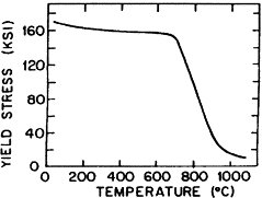
Fig. 22 Shear strength of Inconel 718 vs. temperature
Over many years, many feasibility studies have been performed with the use of intense heat to locally soften the work material prior to the cutting tool in an attempt to improve machinability of difficult-to-cut materials. Processes such as laser-assisted machining (LAM) and plasma enhanced machining (PEM) are two most promising techniques that have been developed because they can provide the necessary heat intensities required to soften the workpiece. It has been experimentally shown that using either of these methods can extend the tool life and also improve the roughness of the machined surface [1, 2, 3 and 4]. Although these feasibility studies have not necessarily been performed under optimal conditions, significant improvement of machinability has been reported. Therefore, more improvements are potentially achievable.
Despite the earlier sign of its potentials, the high cost of high power lasers prevented LAM from being widely adopted by industry for the machining of high temperature alloys. Plasma-assisted machining is an economic alternative. PEM can offer comparable heating rates to lasers at a significantly lower cost. In order to adopt PEM for industrial applications, their characteristics must be fully understood so that optimal machining conditions can be achieved. Workpiece temperature plays an important role in the chip formation during the metal cutting process as it affects the material deformation. The large amount of energy generated due to the bulk deformation and friction is almost exclusively converted to thermal energy, leading to high chip and tool cutting temperatures. Temperature in the workpiece is especially important when thermally enhanced machining is used. The effects of externally applied heat sources on the temperature distribution of the workpiece must be known. Peak temperatures must be known so that thermal damage is prevented or minimized in the workpiece surface, and the temperature must be known at the cutting point to control the process. The ability to predict the temperature distribution is the first step in optimizing thermally enhanced machining.
PEM has been systematically analyzed in terms of heating and operating parameters to realize process control and optimization[5]. First, surface temperature of a rotating workpiece is characterized in terms of heating and operating conditions, by numerical modeling as well as radiation thermometry. For numerical modeling, a finite difference model is developed to numerically obtain the temperature distribution of the workpiece. The validity of the model is evaluated by comparing the results with experimental results. For comparison with experimental results, a calibration of emissivity to Inconel 718 is conducted to obtain correct surface temperatures from the spectral temperature measurements using the radiation thermometer. The model is then used to investigate how different heating conditions and machining operating parameters affect the temperature distribution. The resultant process characteristics during PEM are analyzed under a wide range of operating conditions. Also, the results on the surface quality and tool wear are described.
The ability to generate and transfer the desired degree of localized heating to the workpiece is critical to the success of PEM. Heating of PEM is provided by direct current (dc), transferred arcs which generate thermal or equilibrium plasmas. Thermal arc plasma generators consist of a thoriated tungsten cathode and a cooled nozzle through which the plasma gas flows (Fig. 23). The nozzle serves as anode when used with non-conducting workpieces, while, with conducting materials, the arc is transferred to the workpiece which works as anode. With highly localized energy available at low gas flow rates, transfer arcs are well suited to PEM for electrically conducting superalloys, with typical plasma peak temperature reaching 16000°K.
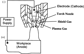
Fig. 23 Details of a plasma arc (transferred arc) generator.
Experimental evaluation of PEM was performed on a plasma enhanced machining system which consists of a 7 HP
lathe, a plasma heating system with a torch and a control unit[5]. To minimize the effect of the turbulent air flow generated by the rotating chuck, a special enclosure was designed and attached to the chuck. It was discovered that the turbulent air flow could affect the plasma arc when cutting is performed near the chuck, leading to inconsistent results. This modification practically eliminated this problem. The plasma torch was fitted with a copper nozzle of 3.18 mm. orifice diameter. Thoriated tungsten cathodes with a 20 degree included angle were used throughout the experiments.
The picture of the overall experimental set-up is shown in Fig. 24
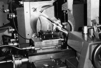
Fig. 24 Experimental set-up of PEM[5]
An accurate model of an underlying experimental system is necessary to conduct parametric studies to characterize temperature distribution during thermally assisted machining. The above experimental system is plasma heating of a turning workpiece undergoing translational feed. This process is the necessary component in plasma enhanced machining (PEM). The intent for creating a finite difference model is to determine the temperature distribution in a turned workpiece which undergoes an intense local heating via a moving plasma jet or a laser. Due to the difficulties associated with spatial temperature measurement, current temperature measurement is limited to the spot temperature on the surface. Therefore, analytical determination of the temperature distribution is important so that heating conditions can be optimized to desired machining conditions. The radial depth of heat penetration, for example, must be minimized to the depth of cut while maintaining a high surface temperature so that the desired material properties at the subsurface are not compromised. The heat transfer problem is formulated based on a fixed coordinate cylinder with three dimensional conduction, rotational advection, and translational advection.
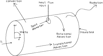
Fig. 25 Schematic of the heat transfer modes considered in the FEM model
The applicable heat transfer modes for this problem are (see Fig. 25):
1. conduction in three dimensions,
2. convection from the outer surface to the surroundings,
3. radiation from the outer surface to the surroundings,
4. advection in the radial direction due to the rotation of the workpiece,
5. advection in the axial direction due to the feed rate, and
6. heat flow into select surface elements from the intense heat source.
For details of the modeling, the readers are referred to [5].
PEM experiments of Inconel 718 with WG-300 inserts (aluminum oxide reinforced with silicon carbide whiskers) were performed at various cutting speeds under a wide range of workpiece surface temperatures (20~700°C). Figure 26 shows the resultant cutting forces measured during PEM. For all the cutting speeds adopted, it can be seen that the cutting force decreases with increasing surface temperature up to 30% near 600°C. This reduction of cutting forces demonstrates the decrease of shear strength of Inconel 718 at an elevated temperature. The actual shear plane temperature would be higher than the surface temperature measured prior to machining due to the additional energy dissipated by plastic deformation.
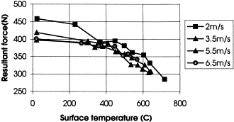
Fig. 26 Resultant cutting force vs. surface temperature for various cutting speeds (operating conditions: FEED=0.124 mm/rev, cutoff LENGTH=0.8 mm, cutting time 0.5 min).
Figure 27 shows the comparison of shear energy for three different cases: conventional machining with a carbide insert, conventional machining with a ceramic insert, and PEM. The specific shear energy with a ceramic insert is much lower than the carbide case since a higher machining speed can be adopted. With a similar cutting speed, however, the shear energy can be further reduced by plasma heating of the workpiece. This trend explains the reduction of cutting force with the increasing workpiece temperature.
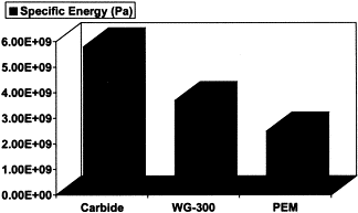
Fig. 27 Comparison of specific shear energy for conventional machining with carbide and ceramic inserts, and PEM.
Improvement of surface roughness with PEM was also evaluated by varying surface temperature for different cutting speeds. Figure 28 shows the experimental results in the range of 20 to 700°C in temperature for four cutting speeds of 2, 3.5, 5.5 and 6.5 m/sec. In all the cases, a significant improvement of surface roughness could be achieved as the surface temperature was increased to 500°C. Beyond 530°C, surface oxidation was observed sometimes, which deteriorated surface quality slightly. This oxidation is due to the heating by the plasma arc on the finished surface. More accurate control of the plasma arc would minimize this problem.
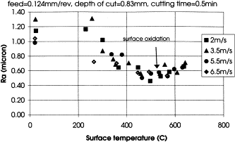
Fig. 28 Surface roughness vs. surface temperature for various cutting speeds (operating condition: FEED=0.124 mm/rev, cutoff LENGTH=0.8 mm, cutting time 0.5 min).
Figure 29 compares the productivity of conventional machining using carbide, WG-300 and WG-300 with PEM. Total metal removed over the life of a carbide tool decreases significantly with increasing metal removal rates. Conventional machining using WG-300 results in high metal removal rates, but tool life is limited. Alternatively, PEM using WG-300 enables high metal removal rates and increased tool life compared to conventional machining. In general, the chip temperature is a little higher in PEM than in conventional machining, leading to higher flank wear rates. However, deep notching, which was the predominant mode of tool failure in conventional machining of Inconel 718, was virtually eliminated, thereby resulting in longer tool life.
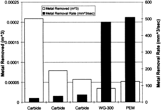
Fig. 29 A comparison between conventional machining and PEM considering the amount of metal removed over the life of a tool and the metal removal.
5.2 Laser Assisted Machining of Ceramics
Laser assisted machining (LAM) has recently been considered as an alternative process for machining ceramic materials. In LAM, the laser is used as an intense heat source to change the ceramic deformation behavior from brittle to ductile just prior to material removal, without melting or sublimation of the workpiece. Ceramics can exhibit brittle fracture or plastic deformation, depending on their composition and microstructure, as well as the mechanical conditions to which they are subjected to. For example, silicon nitrides retain their room-temperature strength to a high temperature, beyond which they exhibit a strength reduction [7-10,15,17, and 20]. This reduction is typically due to softening of a glassy phase at the grain boundaries, which induces inelastic behavior. With YSiAlON glass used as a sintering agent and subsequent heat treatment to nearly complete crystallization, Cinibulk et al. [7] demonstrated strength retention of silicon nitride to temperatures as high as 1000°C. At low temperatures below the softening point of the glassy phase, material failure is mainly caused by transgranular fracture, while at high temperatures, the fracture surface is predominantly intergranular [15].
Some ceramics can be deformed superplastically to a very large strain, much larger than that obtainable in typical four-point bending and creep experiments. Superplasticity in ceramics takes place at low stress levels, high temperatures and with low strain rates. Fine-grained silicon nitride ceramics also exhibit superplasticity under certain conditions. Wang et al. [18] and Burger et al. [6] studied the superplastic behavior of silicon nitride using a compression test, and obtained compressive strains of 0.4 and 0.69, respectively. They attributed the superplastic deformation to grain-boundary sliding, which is influenced by the characteristics of the intergranular glassy phase. Strain hardening has been observed during superplastic deformation of ceramics. Wang et al. [19] have shown that strain hardening in 3Y-TZP (yttria-stabilized tetragonal zirconia) is caused by an increased resistance to the sliding and rotating of grains as they become elongated during superplastic extension. Burger et al. [6] attributed strain hardening in a low-doped silicon nitride to rigid and dry grain-to-grain contacts which result from liquid-like glassy phase being squeezed from the grain boundaries.
During LAM, material is removed at high temperatures and high strain rates. Material removal mechanisms associated with LAM will be inferred from a microscopic [scanning electron microscopy (SEM)] analysis of the resulting chips.
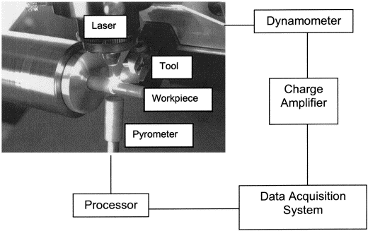
Fig. 30 Experimental system for LAM of silicon nitride
Sample chips from the LAM experiments were collected and coated with gold for SEM investigation. Under a very high temperature, semi continuous chips are formed during LAM of ceramics, indicating plastic deformation rather than brittle fracture. The picture below shows the SEM micrograph of a continuous chip taken under after LAM of silicon nitride parts.

Fig. 31 SEM micrograph of a continuous chip in LAM of silicon nitride
Material removal mechanisms due to cutting in LAM are summarized as follows. When the workpiece temperature increases and exceeds the glass transition temperature of the intergranular glassy phase, the viscosity of the glassy-phase material decreases and the rod-like Si3N4 grains are mobilized. Under the load of the cutting tool, the Si3N4 grains at the shear deformation zone begin to slip at the grain boundaries, rotate and experience mutual interactions. At the same time, the fluid-like glassy-phase material flows and redistributes along the grain boundaries and the grain-junction pockets. At this stage, the material deforms plastically. It is the intergranular glassy phase that joins the Si3N4 grains and sustains the plastic deformation. Without the glassy grain-boundary phase, the workpiece material would fracture immediately during removal.
Accordingly, there are two principal mechanisms associated with material removal by a cutting tool in LAM: (1) material plastic flow of a glassy grain-boundary phase with reorientation of -Si3N4 grains, and (2) nucleation and propagation of intergranular microcracks which result in segmented chip formation. During the process, the Si3N4 grains behave as rigid bodies, and mutual interaction could cause occasional transgranular fracture, which is manifested by the shorter grains seen in SEM micrographs of the chips. As deformation approaches the second stage, the newly formed grain boundaries and the grain-junction pockets are depleted of glassy-phase material. Intergranular cracks are then initiated and subsequently coalesce and propagate along the shear zone until a chip segment is formed and separated from the workpiece. Material removal is realized in the form of segmented chips as the process proceeds.
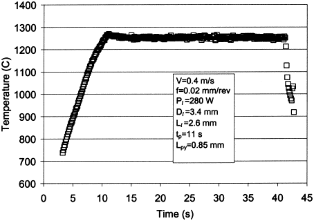
Fig. 32. Variation of the measured workpiece surface temperature with machining time
Workpiece surface temperature and cutting force histories were measured on-line for each experiment, and representative results are shown in Fig. 32 and Fig. 33, respectively. It was observed that intense surface heating can oxidize, melt and/or vaporize workpiece surface material and that the transient thermal response of the workpiece can induce uneven thermal expansion of the material. These effects were considered in determining the actual depth of cut by subtracting the thickness of the heat-removed layer and the machined surface diameter from the as-received workpiece diameter. All three force components show similar trends, with no increase in the forces during machining. For all of the cases, it was found that cutting forces were not influenced by tool wear within the measurement sensitivity of the experiment. This is attributed to the nature of the deformation process and to the nature of tool wear associated with LAM. In particular, during LAM, a thin coating of workpiece glassy material adheres to the wear land of the tool flank, and unlike metal cutting, where severe friction occurs between a flank wear land and a freshly machined surface, the viscous glassy material on the wear land acts as a lubricant and there is no significant influence of tool wear on the cutting force.
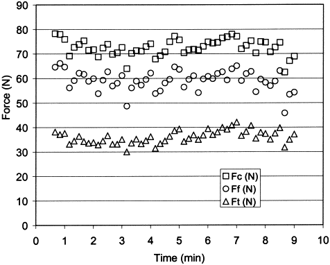
Fig. 33 Variation of cutting force components with machining time
The shear zone stress was calculated using three-dimensional machining theory [13 and 16] with knowledge of the machining conditions (cutting speed, feed and depth of cut), the cutting forces and the shear angle. It is concluded that the stress decreases with increasing temperature due to a reduction in material strength. As temperature increases, the viscosity of the glassy boundary phase decreases, thereby facilitating its flow and thus requiring reduced stress to deform the material. It is also concluded that, for the range of cutting speeds used in the LAM experiments, the stress is not strongly affected by cutting speed. Since the strain rate increases with cutting speed, this result suggests that the effect of the strain rate on the stress is not significant for the conditions of this study. The decrease in the stress with increasing feed is attributed to an attendant decrease in the average shear zone strain with increasing feed. The decrease of shear zone strain with feed is known to characterize metal cutting [12 and 13]. In addition, finite element simulations have shown that strain decreases steeply along the shear plane for a small feed, with the maximum value at the tool tip [11 and 14]. For the small feeds used in LAM, the length of the shear plane increases with increasing feed, thereby reducing the average strain in the shear zone.
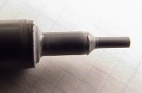
Fig. 34 A LAM machined silicon carbide parts (Courtecy of Laser Materials Processing Lab., Purdue University)
The benefits of LAM include:
- Laser-assisted machining offers a flexibility in manufacturing which is currently not available for medium to high volume ceramic machining.
- Compared to grinding, LAM offers: higher material removal rates, little or no sub-surface damage, faster set-up, more flexibility in using multiple inserts and changing part programs. An average surface roughness of 0.3 microns can be achieved during LAM of silicon nitride.
- The power, beam diameter, heat flux and targeting of the laser heat source can be easily controlled, both continuous wave or pulsed modes, and a variety of wavelengths can be varied.
- A single laser can be time-shared by multiple machining stations.
Comment:
The two processes in this section enlighten us that the property of material is relative. By changing the thermal state of high temperature alloys and ceramics, their machinability changes. An opposite application of thermal field is to machine soft materials at low temperatures. All in all, when we run across difficulties in normal conditions, let's try to change the machining condition-the thermal field, chemical field, electrochemical field, electromagnetic field, or even the gravity field, pressure filed, and the medium field! Well, there are many ways to go when one way is prove to be too difficult.
References
1. R. Komanduri, D.G. Flom and M. Lee, Highlights of the DARPA Advanced Machining Research Program. Transactions of the ASME, Journal of Engineering for Industry 107 (1985), pp. 325-335.
2. T. Kitagawa, K. Katsuhiro and A. Kubo, Plasma hot machining for high hardness metals. Bull. Japan Society of Precision Engineering 22 2 (1988), pp. 145-151.
3. W. König, L. Cronjäger, G. Spur, H.K. Tönshoff, M. Vigneau and W.J. Zdeblick. Annals of the CIRP 39 2 (1990), pp. 673-681.
4. J.W. Novak, Y.C. Shin and F.P. Incropera, Assessment of plasma enhanced machining of improved machinability of Inconel 718. Transactions of ASME, Journal of Manufacturing Science and Engineering 119 (1997), pp. 125¯129.
5. Carl E. Leshock, Jin-Nam Kim, and yung C. Shin, 2001,"Plasma enhanced machining of Inconel 718:modeling of workpiece temperature with plasma heating and experimental results," Int. J. Machine Tools & Manu., Vol. 41, 2001, pp. 877-897.
6. P. Burger, R. Duclos and J. Crampon, Superplastic behavior of low-doped silicon nitride. Materials Science and Engineering A222 (1997), pp. 175-181.
7. M.K. Cinibulk, G. Thomas and S.M. Johnson, Grain-boundary-phase crystallization and strength of silicon nitride sintered with a YSiAlON glass. Journal of the American Ceramic Society 73 6 (1990), pp. 1606-1612.
8. S. Hampshire, Engineering properties of nitrides, ceramics and glasses. In: Engineered Materials Handbook vol. 4, ASM International, OH (1991), pp. 812-820.
9. F.F. Lange, Dense Si3N4 and SiC: some critical properties for gas turbine application. ASME Paper 72-GT-56, American Society of Mechanical Engineers, New York (1972).
10. F.F. Lange, Silicon nitride polyphase systems: fabrication, microstructure, and properties. International Metals Reviews 25 1 (1980), pp. 1-20.
11. S. Lei, Y.C. Shin and F.P. Incropera, Thermo-mechanical modeling of orthogonal machining process by finite element analysis. International Journal of Machine Tools and Manufacture 39 5 (1999), pp. 731-750.
12. P.L.B. Oxley. The Mechanics of Machining: An Analytical Approach to Assessing Machinability, Ellis Horwood Ltd, Chichester (1989).
13. M.C. Shaw. Metal Cutting Principles, Oxford University Press, Oxford (1984).
14. A.J. Shih, Finite element simulation of orthogonal metal cutting. ASME Transactions, Journal of Engineering for Industry 117 (1995), pp. 84-92.
15. J.T. Smith and C.L. Quckenbush, Phase effects in Si3N4 containing Y2O3 or CeO3: I, strength. Ceramic Bulletin 59 5 (1980), pp. 529-537.
16. E. Usui and A. Hirota, Analytical prediction of three dimensional cutting process, Part 2: chip formation and cutting force with conventional single point tool. ASME Transactions, Journal of Engineering for Industry 100 (1978), pp. 229-235.
17. J.B. Wachtman. Mechanical Properties of Ceramics, John Wiley & Sons, Inc, New York (1996).
18. C. Wang, M. Mitomo, T. Nishimura and Y. Bando, Grain boundary film thickness in superplastically deformed silicon nitride. Journal of the American Ceramic Society 80 5 (1997), pp. 1213-1221.
19. Z.C. Wang, N. Ridley and T.J. Davies, Strain hardening and grain elongation during superplastic deformation of ceramics. Journal of Materials Science Letters 14 (1995), pp. 355-357.
20. G. Ziegler, J. Heinrich and G. Wötting, Review: relationships between processing, microstructure and properties of dense and reaction-bonded silicon nitride. Journal of Materials Science 22 (1987), pp. 3041-3086
![]()
![]()